
Vision Application Manual
1. Preface
This manual is intended for engineers involved in industrial automation, including system design, commissioning, maintenance, and product selection. It provides a systematic introduction to the core knowledge of vision applications. The content combines theoretical concepts with practical implementation, covering technical principles, hardware selection, system configuration, troubleshooting, and application scenarios. It is suitable for beginners who need to get started quickly, while also serving as a practical reference for experienced engineers.
Note:
All operations and configurations described in this manual are based on the following software versions. Earlier versions may have missing features or compatibility issues:
- AUBO STUDIO APP: Version 0.9.5-rc.6 or later.
- ARCS System: Version 0.31.1-rc.25 or later.
2. Safety Information
Since a vision system involves robot motion, electrical connections, and other potential hazards, users must carefully read, understand, and follow the instructions in this manual before use. System integrators must ensure that the deployed vision system complies with applicable laws, regulations, and industry standards. Risk assessments must be performed, and appropriate measures must be taken to reduce potential risks. Users must also comply with all safety requirements specified by the system integrator.
Safety Warning
When deploying or operating a vision system, always pay attention to equipment and operational safety. Users are responsible for ensuring their own safety and the safety of the work area. AUBO is not responsible for any accidents or damages caused by improper operation or failure to follow safety regulations.
3. Hardware
3.1 Hikrobot 2D Camera
3.1.1 Introduction
Hikrobot 2D industrial cameras feature high-resolution CMOS sensors and advanced imaging algorithms, delivering excellent performance in defect inspection, positioning guidance, and barcode recognition. The cameras support high-speed communication interfaces such as GigE and USB 3.0. They provide outstanding operational stability and environmental adaptability, enabling accurate image acquisition of high-speed moving objects. These cameras are suitable for a wide range of industrial automation applications while offering an excellent balance between performance and cost.
3.1.2 Wiring
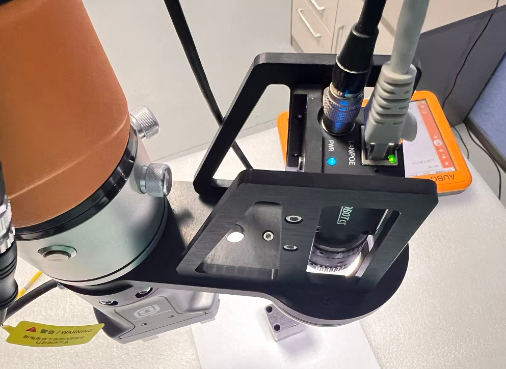
The Hikrobot 2D camera typically has two primary interfaces: one is the data communication interface (available in Gigabit Ethernet and USB versions), and the other is the power and I/O interface for power supply and signal communication.
- Data Communication Interface: Connect the camera to the same network as the controller (ARCS) to establish communication.
- Power and I/O Interface: Connect the dedicated power cable to a DC power supply (typically 12 V or 24 V) to ensure stable operation under heavy workloads.
3.1.3 Connection
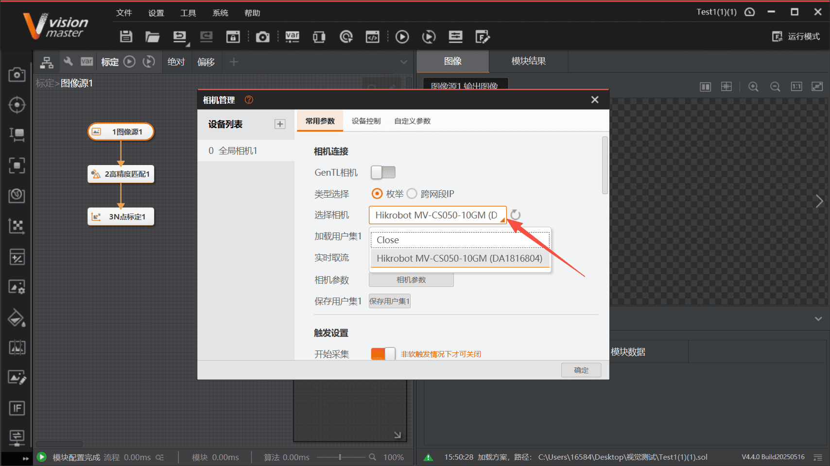
Open the Hikrobot software VisionMaster (VM), then connect to the camera.
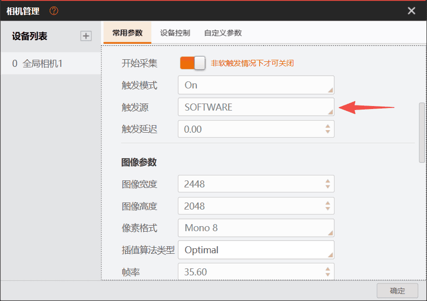
Set the Image Acquisition Trigger Source to SOFTWARE. Otherwise, the software cannot trigger image acquisition correctly.
3.2 Mech-Mind 3D Camera
3.2.1 Overview
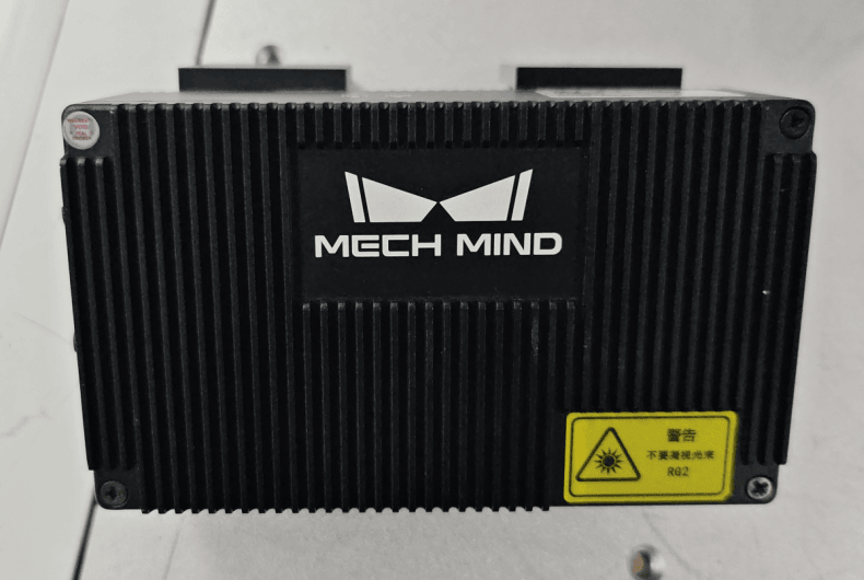
This manual uses the Mech-Eye industrial 3D camera. It features high accuracy, fast acquisition speed, strong resistance to ambient light, and excellent image quality. The camera can generate high-quality 3D point cloud data for objects made of various materials. It meets application requirements at short, medium, and long working distances, providing excellent ambient light resistance, high precision, a wide field of view, high acquisition speed, and a compact design.
Camera:
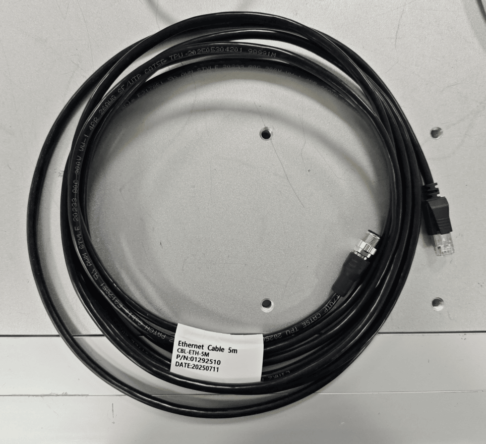
M12-to-RJ45 Ethernet Cable
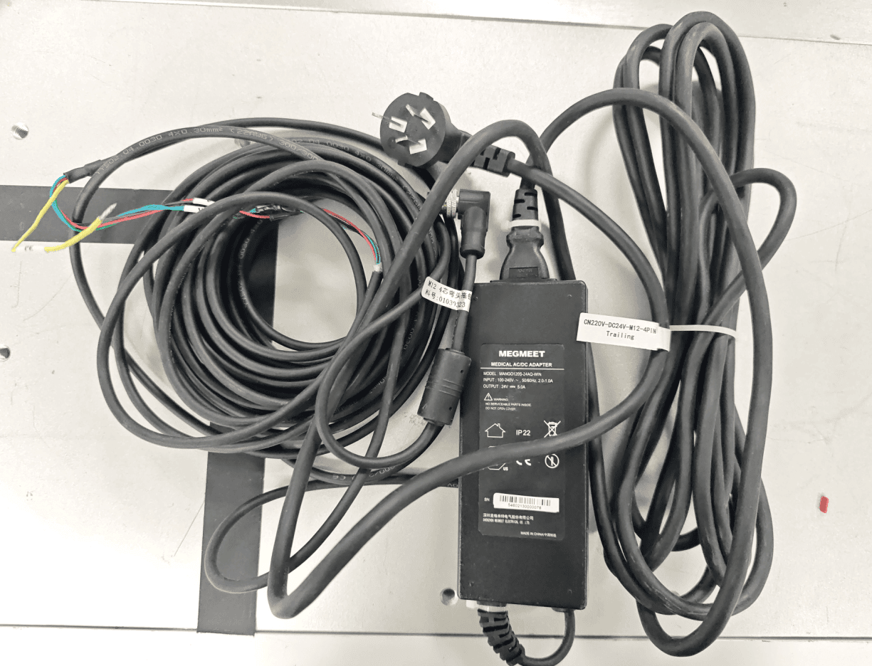
Power Adapter
3.2.2 Wiring
On the camera side, connect the power adapter and the M12 Ethernet cable to the camera. Connect the RJ45 end of the Ethernet cable to a network switch or directly to the industrial PC. Ensure that the camera and industrial PC are on the same subnet.
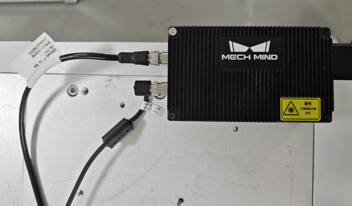
On the industrial PC side, connect the RJ45 Ethernet cable to the network switch. Ensure that the industrial PC and camera are on the same subnet.
3.3 AUBO In-House Camera
3.3.1 Hardware Overview
Hardware Overview: The AUBO in-house camera consists of the camera body, lens, light source, camera power cable, light source power cable, Ethernet cable, and enclosure. The following table lists the key specifications of each component, providing a quick overview of the hardware.
| Component | Parameter | Specification |
|---|---|---|
| Lens | Type | Fixed focal length, manual iris, 6 MP FA lens |
| Lens | Focal Length | 12 mm |
| Lens | F-number | F2.8–F16 |
| Lens | Image Circle | Φ9 mm (1/1.8") |
| Lens | Distortion | -0.005% |
| Lens | Minimum Working Distance | 0.1 m |
| Lens | Field of View | D (8.96 mm): 40.94° H (7.38 mm): 34.14° V (4.92 mm): 23.17° |
| Camera | Sensor Type | CMOS, rolling shutter |
| Camera | Pixel Size | 2.4 μm × 2.4 μm |
| Camera | Sensor Size | 1/1.8" |
| Camera | Resolution | 3072 × 2048 |
| Camera | Maximum Frame Rate | 19.1 fps @ 3072 × 2048 Mono 8 |
| Camera | Monochrome / Color | Monochrome |
| Camera | Typical Power Consumption | 2.4 W @ 12 VDC |
| Camera | Power Supply | 9–24 VDC |
| Camera | IP Rating | IP40 (when the lens and cables are installed correctly) |
| Camera | Weight | Approx. 100 g |
| Light Source | Type | Ring light |
| Light Source | LED Type | SMD |
| Light Source | Color Temperature | 6000–6500 K |
| Light Source | Input Voltage | DC 24 V (Max.) |
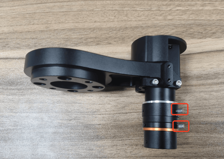
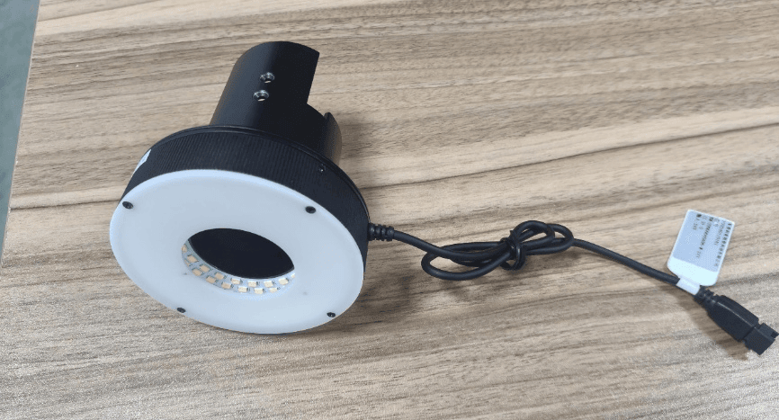
The vision module is shown below. It consists of a lens, camera, and light source.
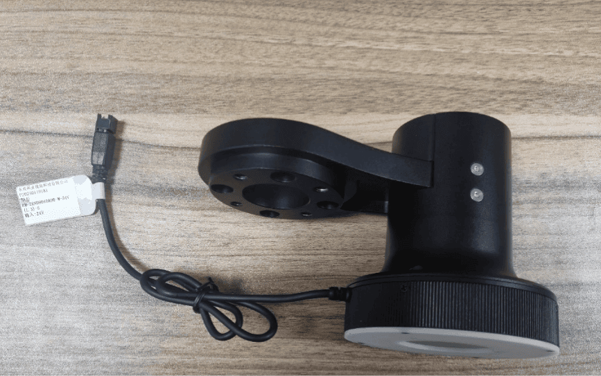
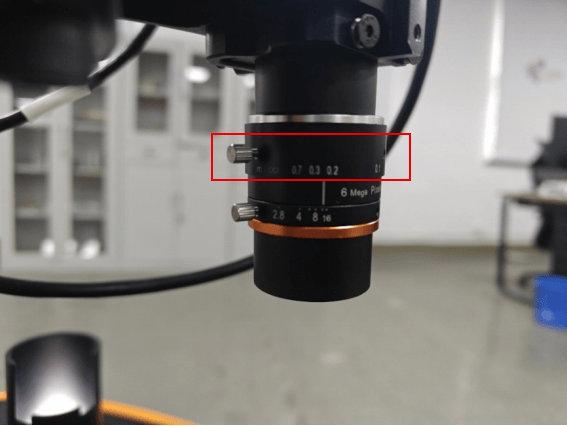
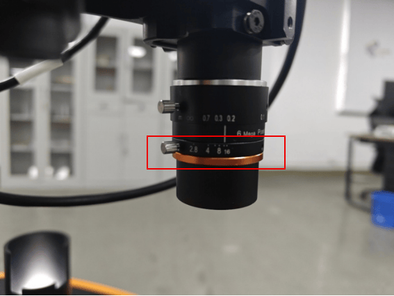
Camera and lens: The camera has two knobs. The upper knob is used to adjust the focal length, and the lower knob is used to adjust the aperture.
Light Source:
3.3.2 Wiring
Check the hardware appearance for obvious damage and ensure that the hardware is in normal condition. After confirming that everything is correct, begin wiring.
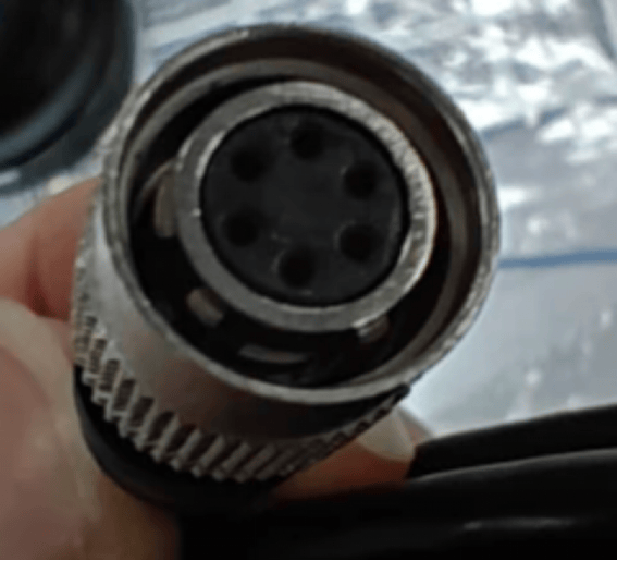
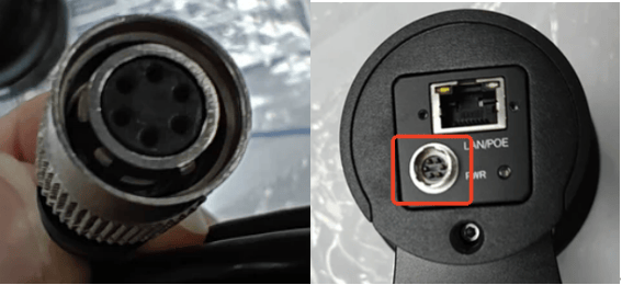
Check that the circular aviation connector on the camera power cable is not deformed or damaged.
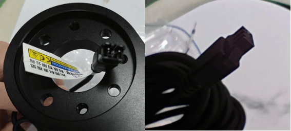
Check that the male and female circular connectors of the light source are not deformed or damaged.
Check that the power interface on the vision camera end is not deformed or damaged, and that the pins are not bent.
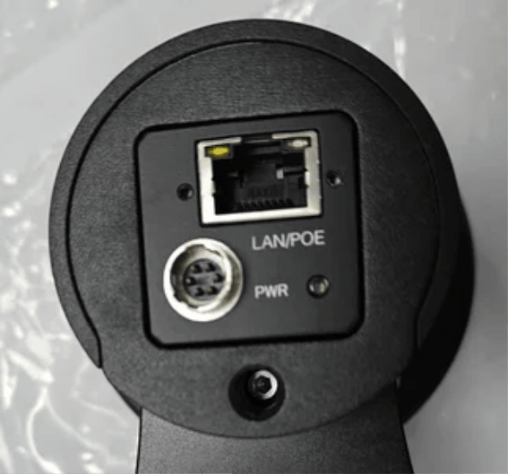
Check that both ends of the power cable are secure and free from damage. After confirming that everything is in good condition, begin the wiring process.
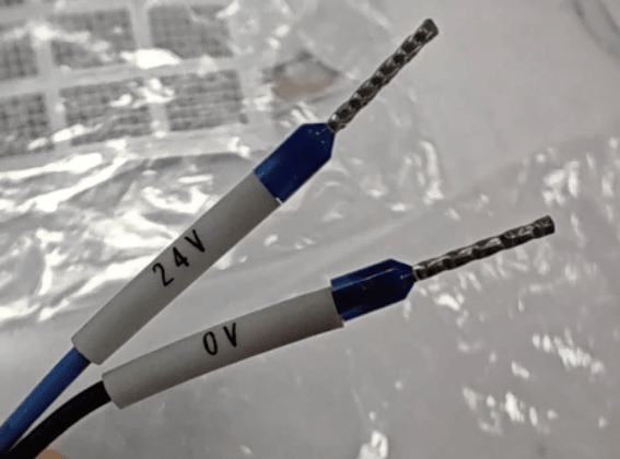
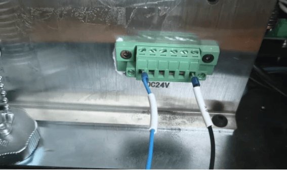
Power off the AMR (Autonomous Mobile Robot), open the rear compartment door, and remove the terminal block from the rear of the AMR.
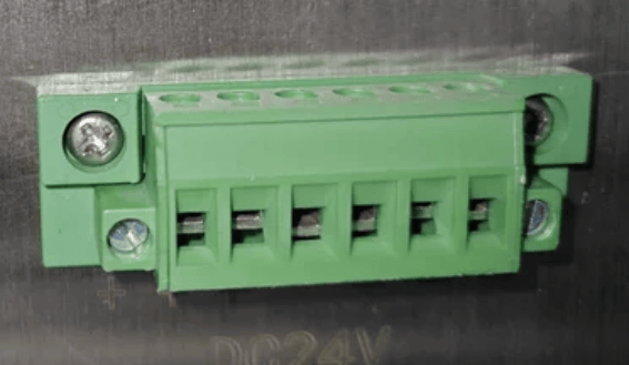
The three terminals on the left are 24 V, and the three terminals on the right are 0 V. Connect the blue 24 V wire and the black 0 V wire to the corresponding terminals, then tighten the screws with a flat-head screwdriver.
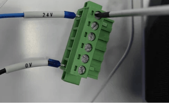
Reinstall the terminal block.
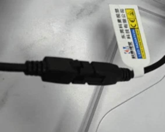
Connect the male and female connectors of the light source power cable.
Connect the camera power cable to the circular connector on the camera.
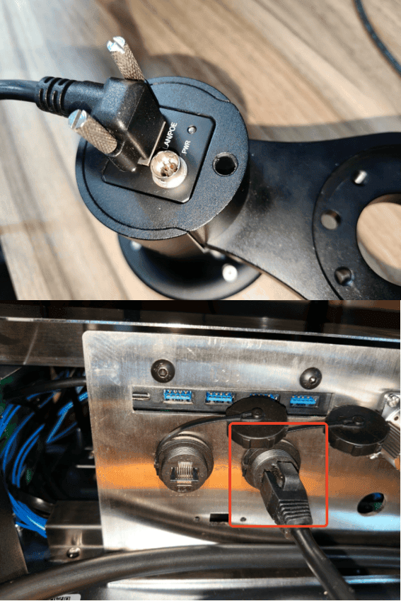
Connect the camera to the Ethernet port on the rear right side of the AMR using an Ethernet cable. Tighten the retaining screws on the camera-side Ethernet connector to prevent it from becoming loose.
4. Camera Communication
4.1 Communication Principles
Currently, the robot and vision device (camera) support the following communication methods:
- Direct TCP/IP Communication Between the Robot and the Camera: Add a Lua script to the program tree to trigger image acquisition and obtain data from the camera. The returned data can be one of the following types:
- Absolute Coordinates: The robot directly obtains the target position.
- Relative Coordinates: The robot obtains the offset distance relative to the current position.
- PLC-Mediated Communication: The camera is connected to the PLC, which triggers image acquisition. After the image is captured, the PLC sends the vision detection results (offset values) to the robot through industrial communication protocols such as Modbus or PROFINET. The robot then performs X-, Y-, and Z-axis offsets based on the received relative position.
4.2 Camera Configuration
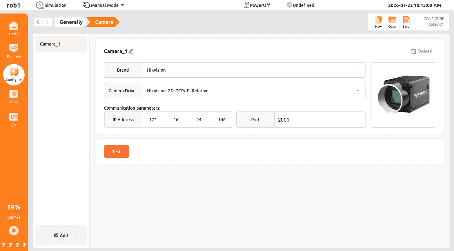
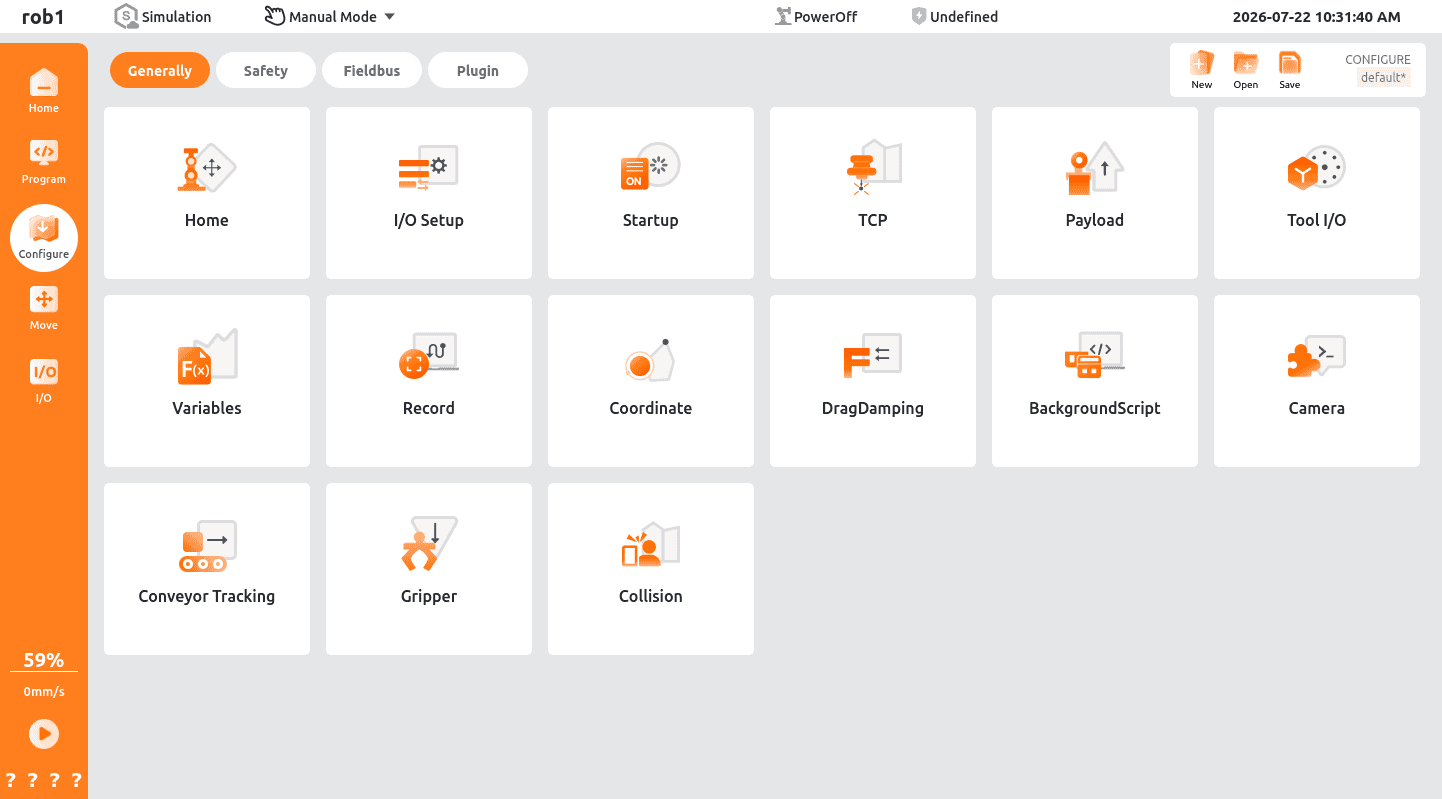
On the ARCS home page, select "Configure > Generally > Camera" from the left navigation pane.
Camera Brand
The drop-down list displays the currently supported camera brands.
Driver Selection
Select the supported driver for the selected camera brand. Both 2D and 3D drivers are available.
Network Configuration
Configure the IP address and port number for communication with the camera (server).
4.3 Lua Script Communication
Lua scripts are the primary method for implementing communication between devices in the ARCS system. They support flexible customization of communication logic and enable data exchange with third-party devices such as cameras, PLCs, and vision systems. The following sections provide templates for the three most commonly used communication scenarios:
TCP/IP Socket Communication: This method is suitable for direct communication between the robot and devices that support the TCP/IP protocol, such as cameras and vision systems. It can be used to trigger image acquisition and retrieve vision results.
Communication Script Template
lua-- Example of camera communication over TCP/IP for image acquisition and data transmission. -- Import the LuaSocket module. local socket = require("socket") -- Set the timeout (unit: seconds). local timeout_seconds = 5 -- Encapsulate the communication process into a function. -- Parameters: server_ip, server_port, message function send_and_receive(server_ip, server_port, message) -- Create a TCP client socket. local client = socket.tcp() -- Create a TCP socket. client:settimeout(timeout_seconds) -- Set the timeout to prevent blocking. -- Attempt to connect to the server. local success, err = client:connect(server_ip, server_port) if not success then textmsg("Failed to connect to the server: " .. tostring(err)) return nil -- Exit the script if the connection fails. end textmsg("Connected to the server: " .. server_ip .. ":" .. server_port) -- Message to be sent. Refer to the communication protocol of the corresponding camera. local bytes, send_err = client:send(message .. "\n") -- Append a newline character so that the server recognizes the message as a complete line. if not bytes then textmsg("Failed to send the message: " .. tostring(send_err)) client:close() textmsg("Disconnected from the server.") return nil else textmsg("Message sent successfully: " .. message) end -- Receive data returned by the server. local response, recv_err = client:receive("*a") -- *a: Read all data. *l: Read a single line. if response then textmsg("Received response from the server: " .. response) -- Process the response as needed. if response == "OK" then textmsg("The server acknowledged the message.") else textmsg("The server returned an unknown response.") end else textmsg("Failed to receive data: " .. tostring(recv_err)) end -- Close the connection. client:close() textmsg("Disconnected from the server.") return response -- Return the server response. end -- Configure the server IP address and port. local server_ip = "192.168.1.100" local server_port = 8080 -- Message to be sent. Refer to the communication protocol of the corresponding camera. local message = "Hello Server" local response = send_and_receive(server_ip, server_port, message) if response then -- Continue processing based on the returned response. endModbus Master Communication: This mode is applicable when the robot acts as the master device and actively reads from or writes to PLC registers. It can be used to send control commands to the PLC and obtain sensor data. It also supports the transmission of complex data types, such as floating-point numbers.
Modbus Master Float Register Access
lua-- Example of reading and writing floating-point numbers using Modbus master communication. function writeModbusFloat(value, lowSignalName, highSignalName) local word = math.float2words(value) local low_word = word[1] local high_word = word[2] modbusSetOutputSignal(highSignalName, high_word) modbusSetOutputSignal(lowSignalName, low_word) end function readModbusFloat(lowSignalName, highSignalName) return math.words2float(modbusGetSignalStatus(lowSignalName), modbusGetSignalStatus(highSignalName)) end -- Example: Read the values from Modbus registers Modbus_0 and Modbus_1, and assign them to the variable P1. -- Note: Reading and writing a floating-point number requires two consecutive Modbus registers. P1 = readModbusFloat("Modbus_0", "Modbus_1") -- Example: Write the floating-point value -3.14 to Modbus registers Modbus_0 and Modbus_1. -- Note: Reading and writing a floating-point number requires two consecutive Modbus registers. writeModbusFloat(-3.14, "Modbus_0", "Modbus_1")Modbus Slave Communication: This mode is applicable when the robot acts as a slave device and passively receives commands and data from a PLC. It enables coordinated control with the production line PLC and supports the receiving and sending of complex data types, such as floating-point numbers.
Modbus Slave Float Register Example
lua-- Example of reading and writing floating-point numbers using Modbus slave communication. function writeModbusFloat(value, low, high) local word = math.float2words(value) local high_word = word[1] local low_word = word[2] setInt16Register(high, high_word) setInt16Register(low, low_word) end function readModbusFloat(low, high) return math.words2float(getInt16Register(high), getInt16Register(low)) end -- Example: Write the floating-point value -3.14 to general-purpose registers 300 and 301 as a Modbus slave. -- Note: Reading and writing a floating-point number requires two consecutive general-purpose registers. writeModbusFloat(-3.14, 0, 1) -- Example: Read the values from general-purpose registers 300 and 301 as a Modbus slave. -- Note: Reading and writing a floating-point number requires two consecutive general-purpose registers. P1 = readModbusFloat(0, 1)
5. Hand-Eye Calibration
5.1 Hand-Eye Calibration Principles
Hand-eye calibration is the foundation of vision-guided robot applications. Its purpose is to determine the coordinate transformation between the camera coordinate system and the robot coordinate system, establishing a mapping matrix between image pixel coordinates and the robot's physical coordinates. This enables the conversion of camera recognition results into robot motion commands.
Core Mathematical Principles The mathematical model of hand-eye calibration can be expressed as the classical AX = XB equation:
- A: Transformation matrix between different robot poses.
- B: Transformation matrix between different camera poses.
- X: Hand-eye transformation matrix to be solved (the transformation between the camera coordinate system and the robot coordinate system).
By collecting multiple sets (typically 9 or more) of robot poses and the corresponding camera images, the transformation matrix can be obtained using nonlinear optimization algorithms. Calibration accuracy is directly related to the number of sampled points, the distribution of the sampled points, and the robot motion increment.
Common Calibration Modes Depending on the camera mounting position, hand-eye calibration is divided into the following two modes:
Calibration Mode Installation Method Application Scenarios Features Eye-to-Hand The camera is fixed on a workbench or bracket and does not move with the robot Position guidance, object recognition, and defect inspection Simple calibration process with a fixed field of view, suitable for static applications Eye-in-Hand The camera is mounted on the robot flange and moves together with the robot. High-precision picking, complex path guidance, and 3D vision inspection High calibration accuracy with a dynamic field of view, suitable for flexible applications The 2D camera calibration procedure in this manual uses the Eye-to-Hand mode, while the 3D camera calibration procedure uses the Eye-in-Hand mode. The actual calibration mode should be selected according to the camera mounting position.
5.2 2D Camera Calibration
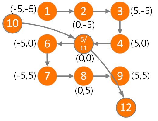
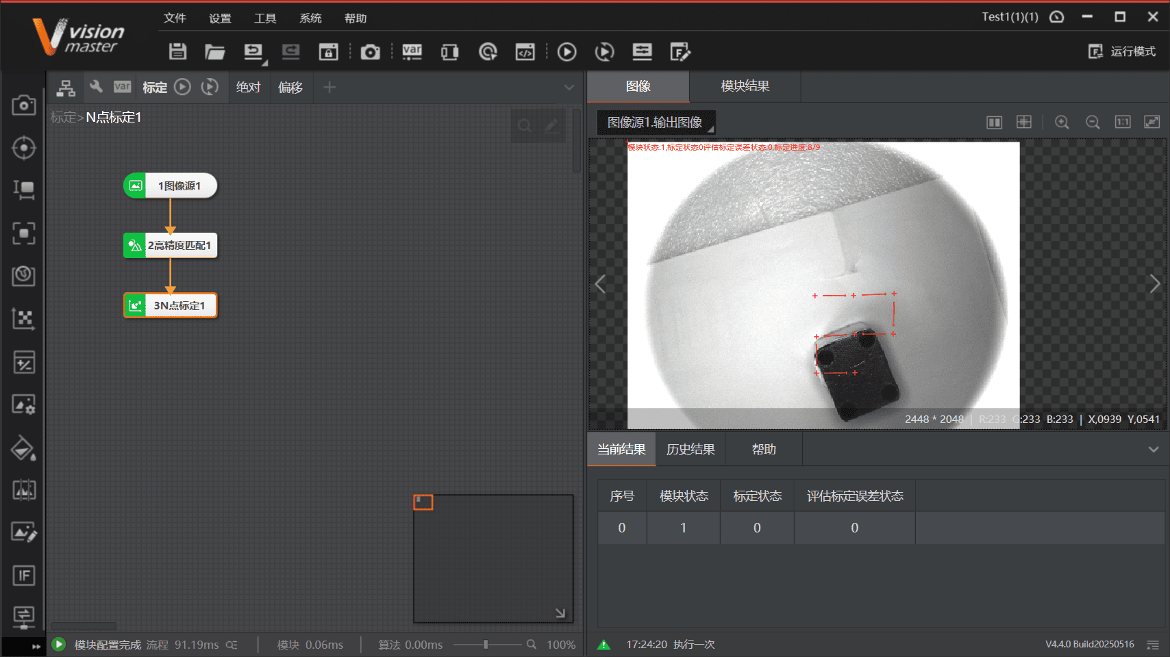
2D camera calibration typically uses the N-point (9-point) calibration method, as shown below.
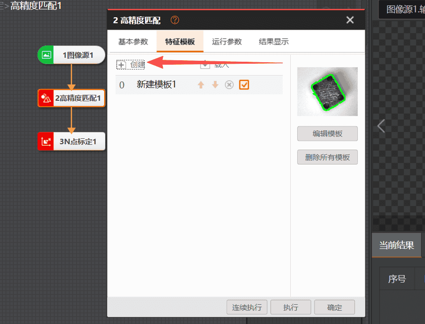
In VisionMaster (VM), add a calibration process by selecting "Image Acquisition > High-Precision Matching > N-Point Calibration".
Add an object template in High-Precision Matching.
In N-Point Calibration, select 9-Point Calibration, enter the offset values, and select the initial movement direction.
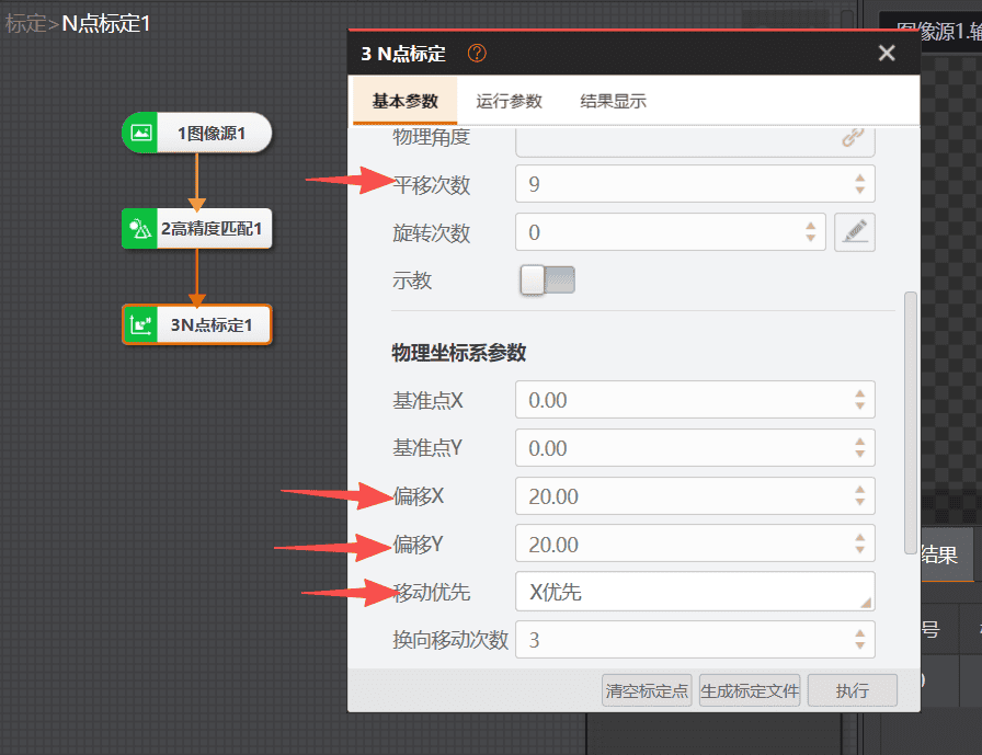
In ARCS, use Jog Mode and teach under the Tool Coordinate System. Set the jog increment to 20 mm for each movement. At the same time, execute the calibration process in VM nine times and record the point information in sequence.
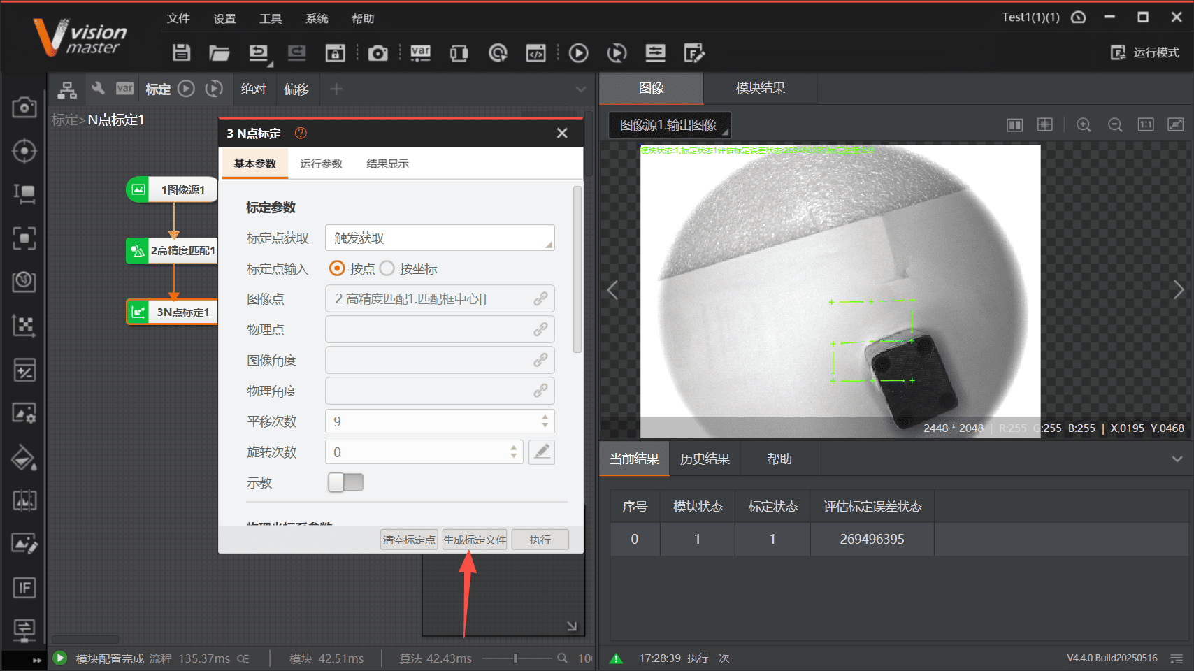
Complete the calibration process, generate the calibration file, and save it.
5.3 3D Camera Calibration
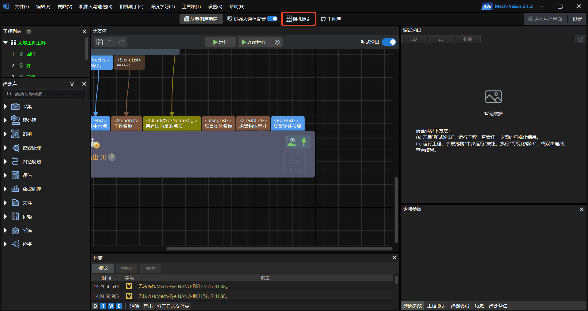
On the Mech-Vision home page, click [Camera Calibration].
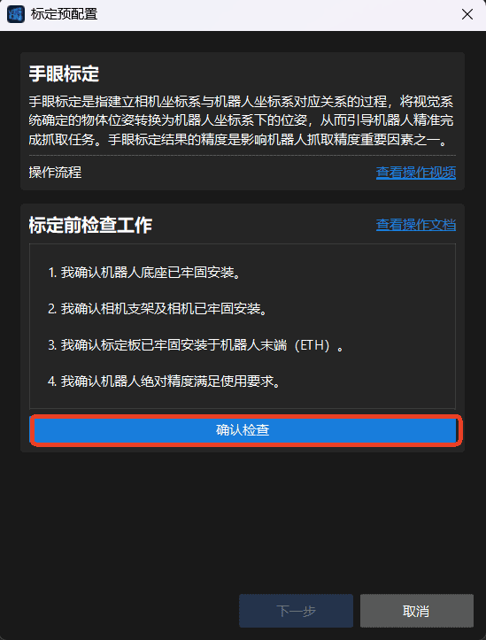
Confirm that the following conditions are met, and then click [Confirm Check]:
Ensure that the robot base is securely mounted.
Ensure that the camera is securely mounted on the robot flange.
Ensure that the calibration board is securely fixed within the robot workspace.
Ensure that the robot absolute accuracy meets the application requirements.
Ensure that the robot has completed the warm-up process.
Start a new calibration.

Select Hand-Eye Calibration for a branded robot, search for AUBO, and select the target robot model.
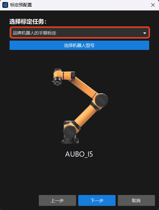
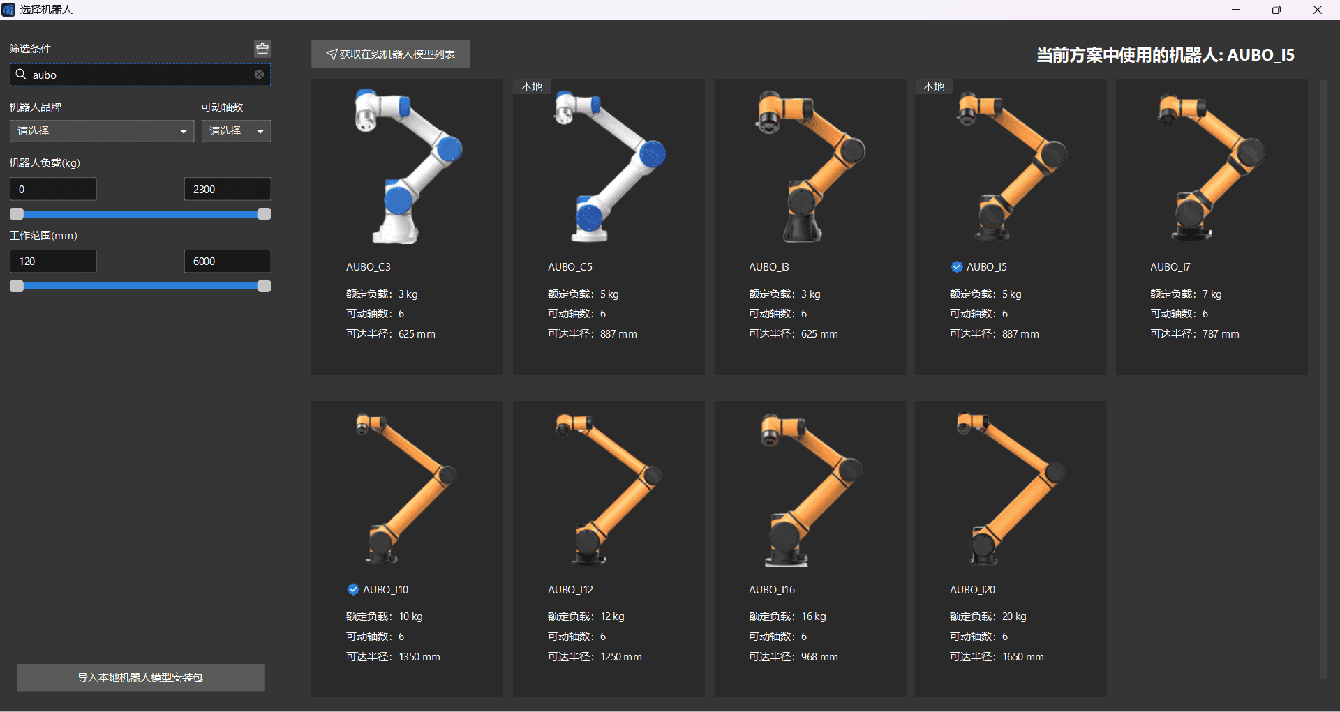
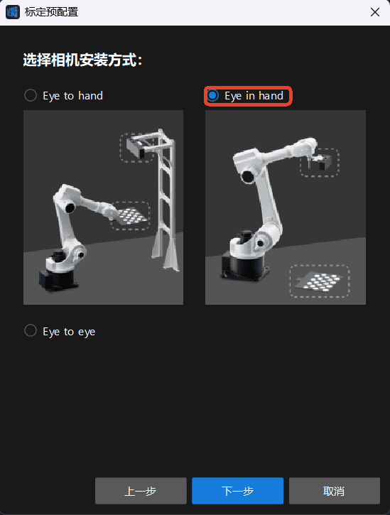
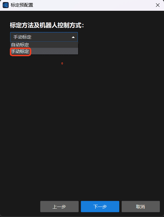
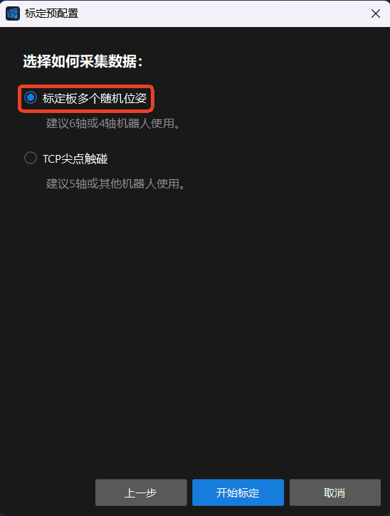
Then select Eye-in-Hand, Manual Calibration, and Multiple Random Calibration Board Poses.
Eye-in-Hand:
Manual Calibration:
Multiple Random Calibration Board Poses:
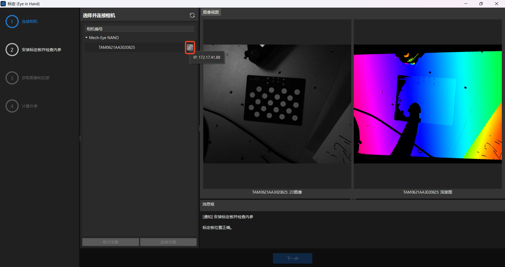
Connect the target camera.
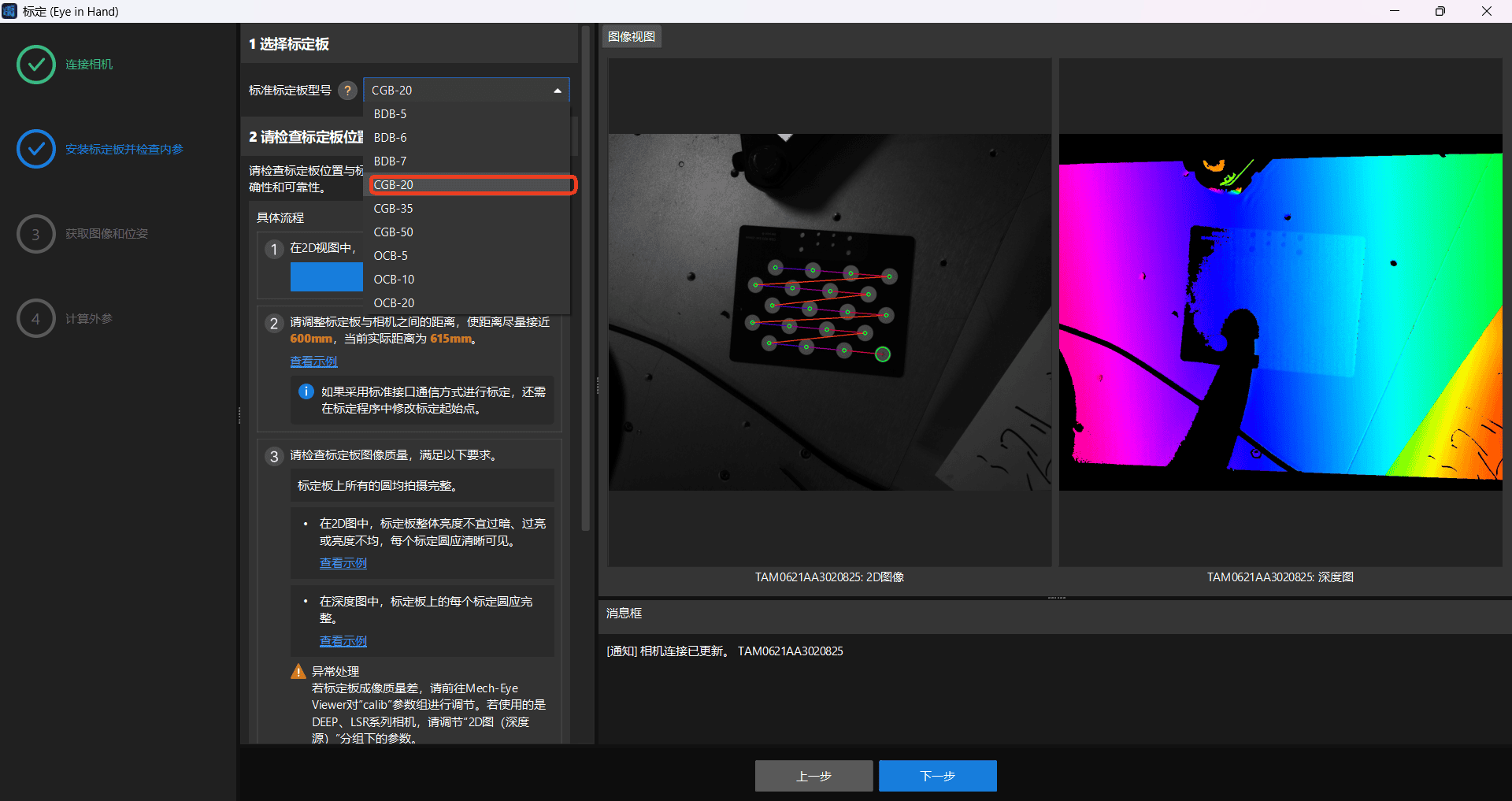
Select the calibration board model in use, and follow the software instructions to verify the calibration board position and image.
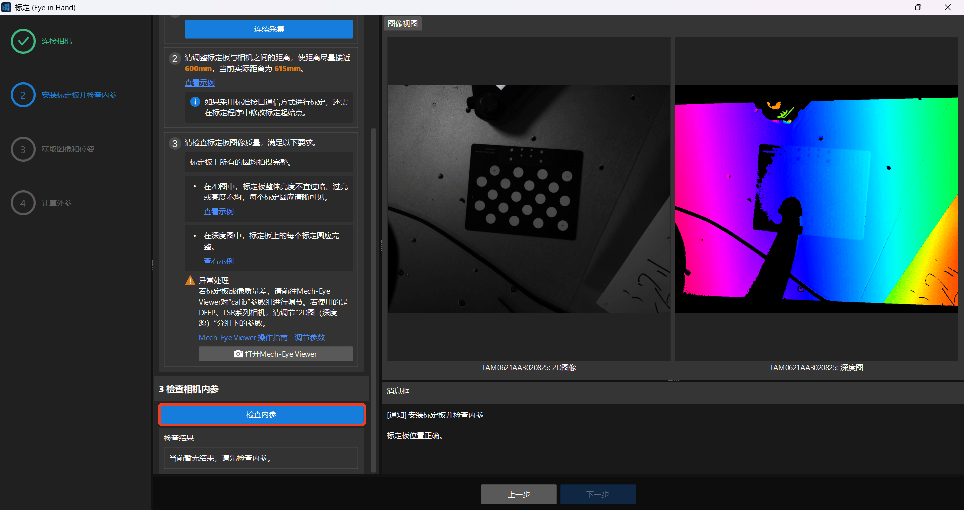
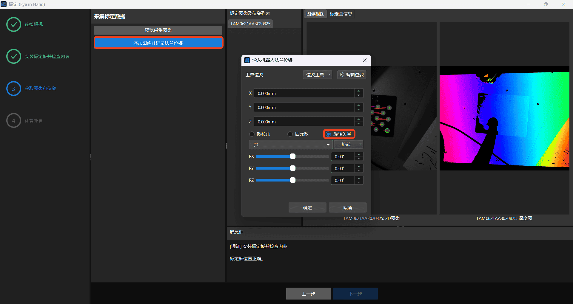
Add images and record the flange poses (at least 20 poses). Select Rotation Vector when recording each pose.
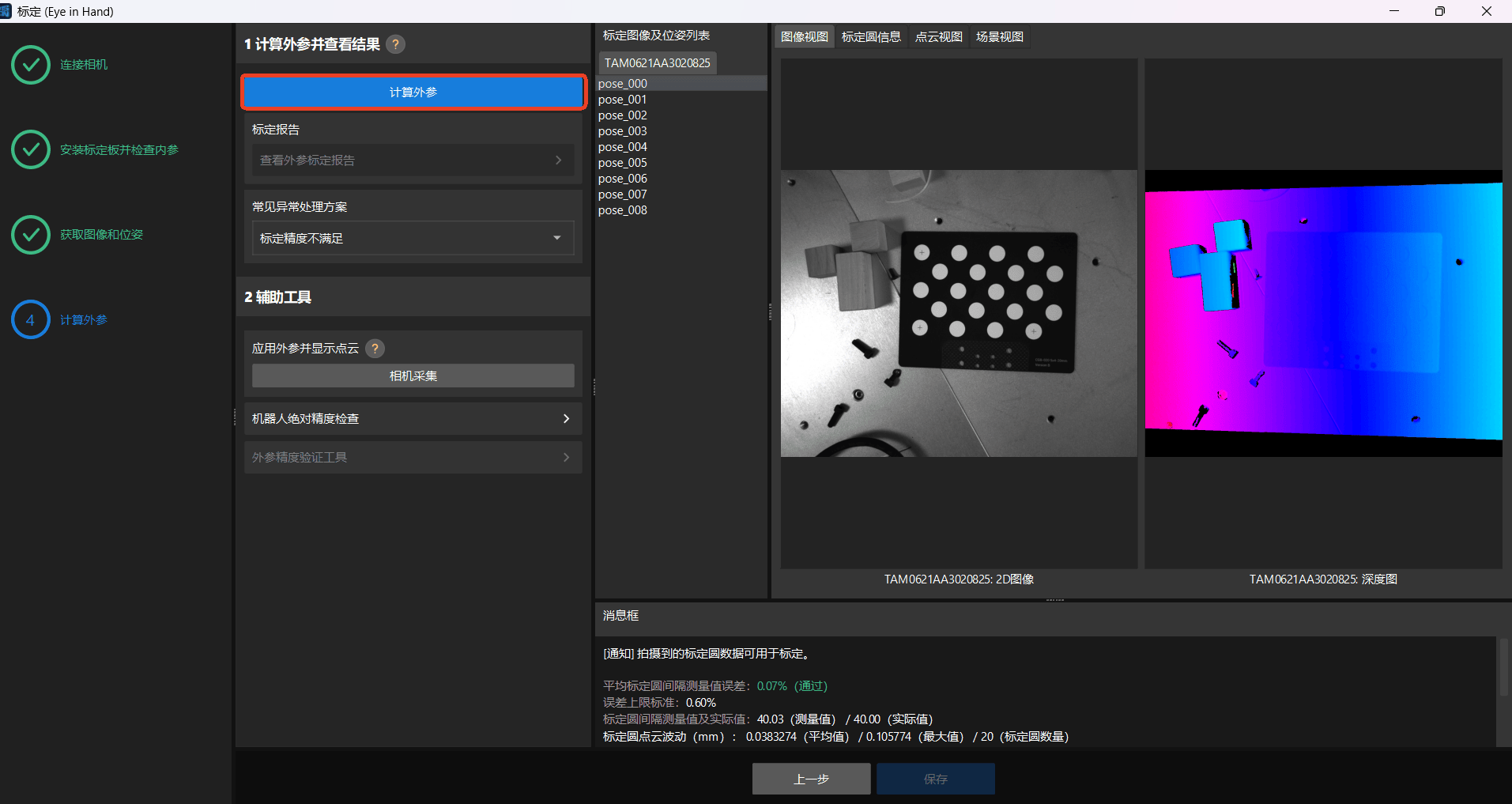
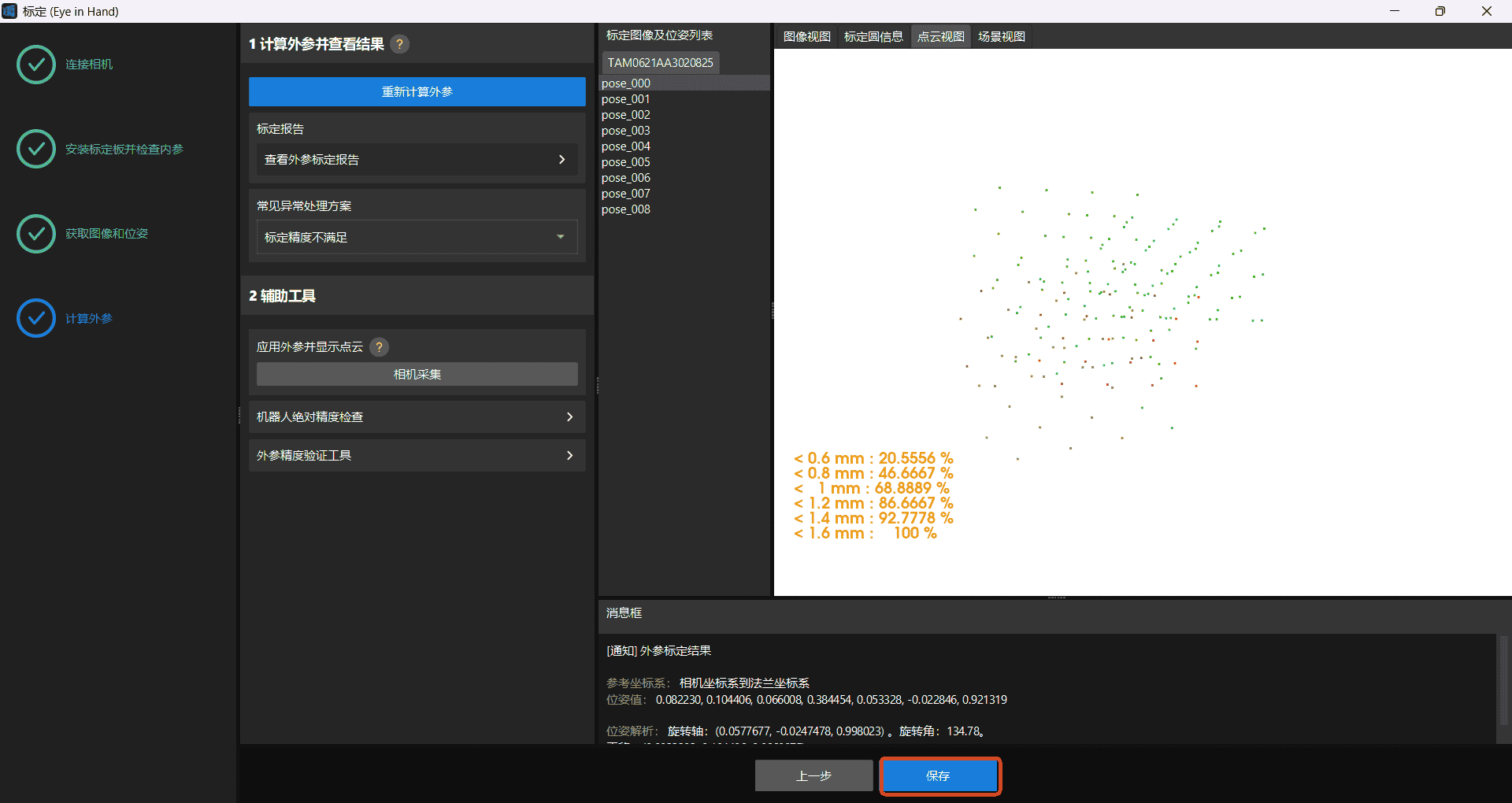
After recording a sufficient number of poses, calculate the extrinsic parameters, save the calibration result, and complete the calibration.
5.4 AUBO In-House Camera Calibration
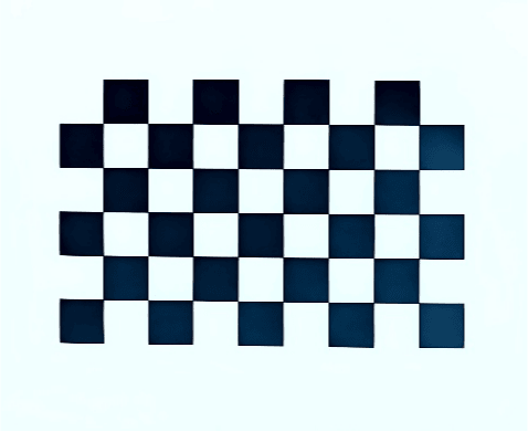
This manual uses a 9 × 6 checkerboard calibration board with a square size of 5 mm.
Note:
Before use, ensure that the checkerboard is clean and undamaged. Do not use checkerboards with other specifications for camera calibration.
Adjust the focal length and exposure
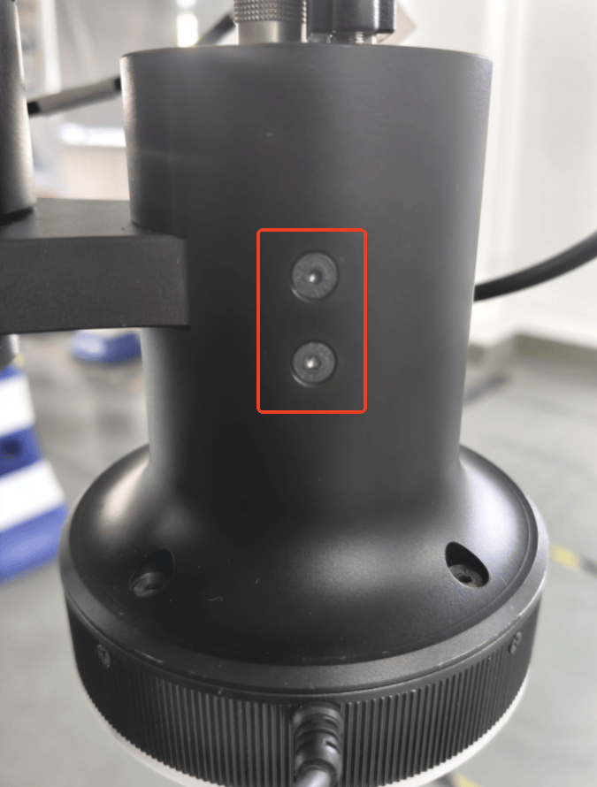
Remove the four screws on both sides of the camera housing.
Note:
Support the camera housing by hand while removing the screws to prevent it from falling.
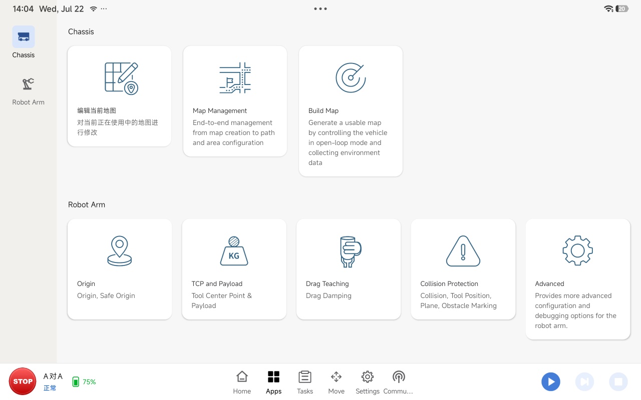
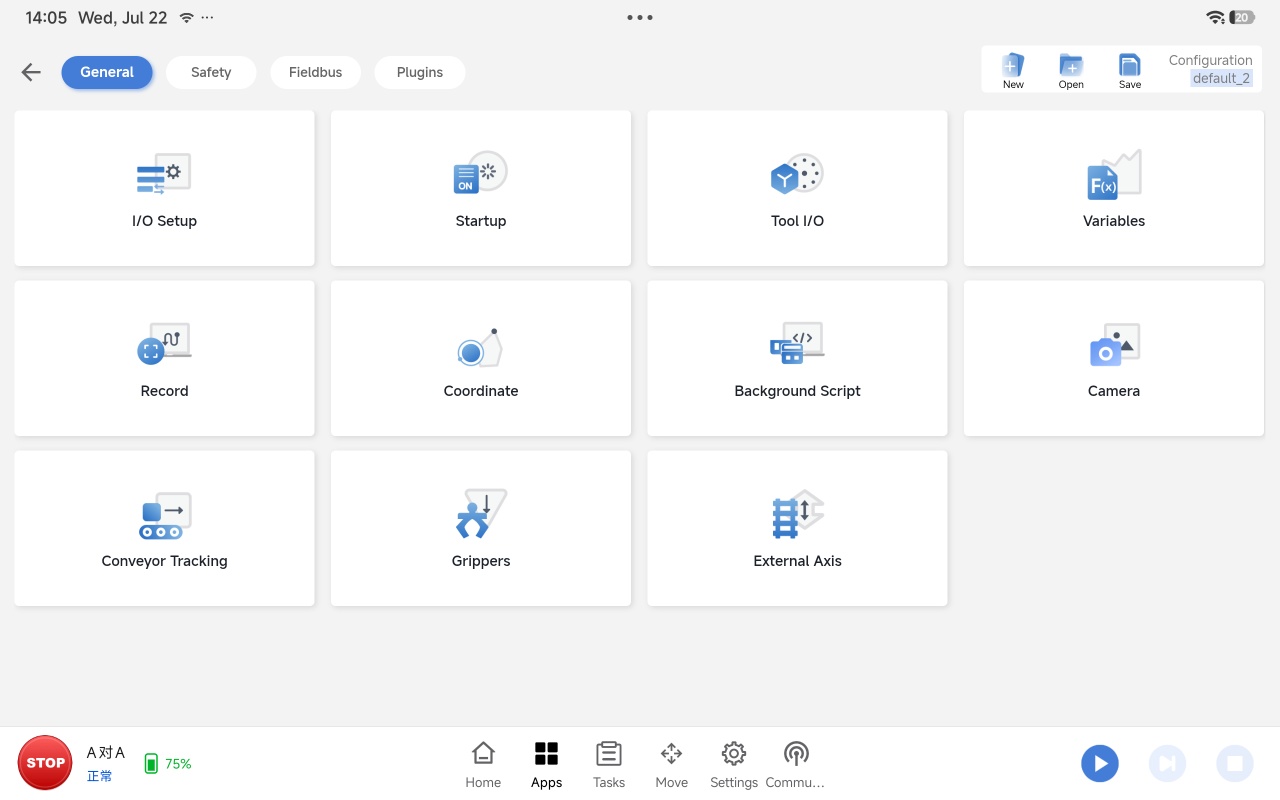
Open the Steering software, then select "Application > Advanced > General > Camera"
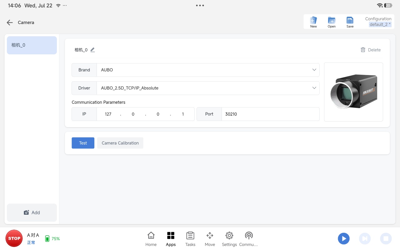
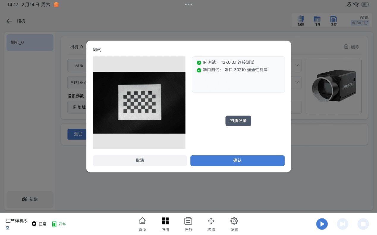
Enter the camera parameters as shown below. After completing the configuration, click [Save] in the upper-right corner, then click [Test] to verify that the camera can capture images correctly.
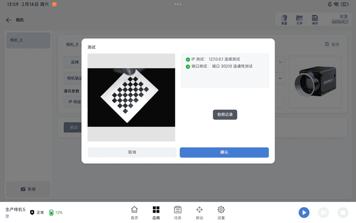
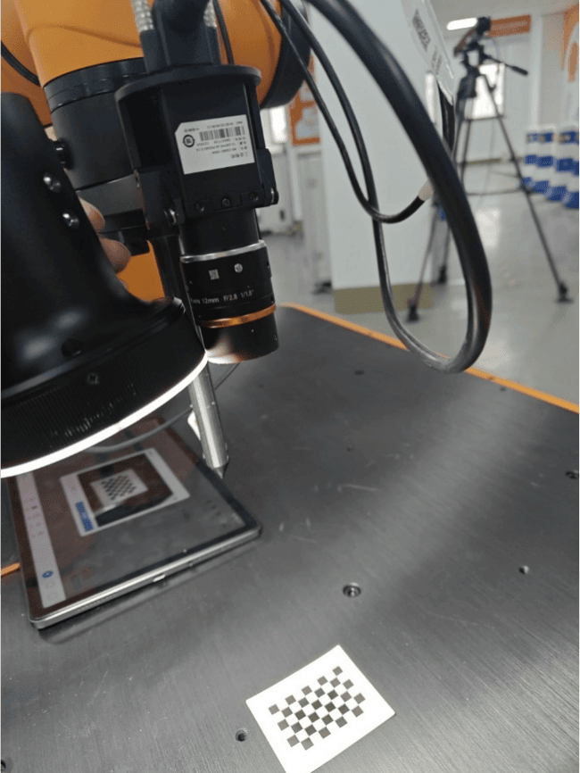
Mount the camera on the robot flange with the flange coordinate system oriented in the X+ and Y- directions. Adjust the robot pose so that the camera is directly above the calibration board and perpendicular to it. Position the calibration board at the center of the camera field of view, with the camera lens approximately 20 cm above the board.
Adjust the focal length:
In the camera test interface, click the capture button to update the camera image. Position the light source close to the lens, slightly loosen the upper locking knob, and rotate the focus ring until the image becomes clear. Then tighten the locking knob.
Adjust the aperture
Position the light source close to the lens, slightly loosen the lower locking knob, and rotate the aperture ring until the captured image is neither too dark nor overexposed. Then tighten the locking knob.
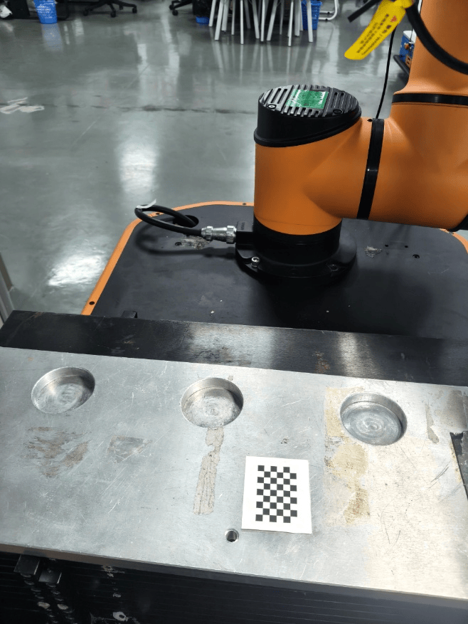
Reinstall the camera housing and power on the robot. Ensure that the camera lens is perpendicular to the calibration board and approximately 20 cm above it. Adjust the calibration board so that it is positioned at the center of the camera field of view.
The edge of the calibration board should face the robot base, as shown below:
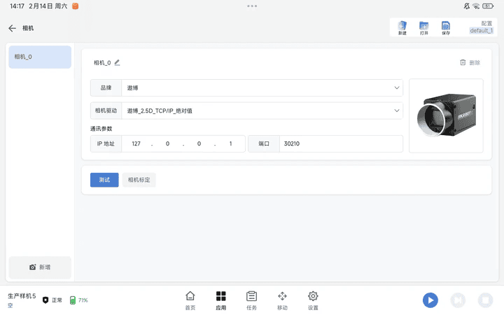
Start camera calibration
Click [Camera Calibration].
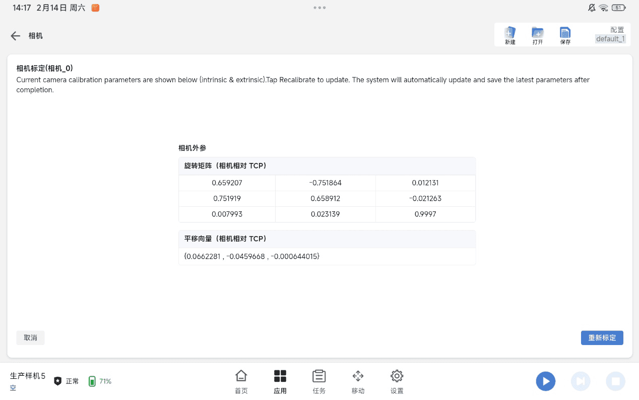
Click [Recalibrate].
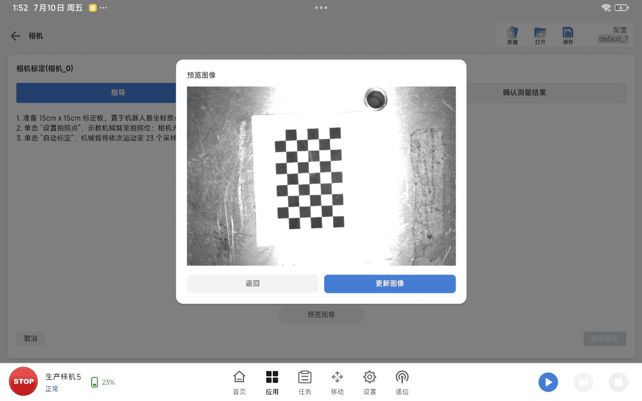
Verify again in the preview image that the calibration board is centered in the camera field of view. After confirmation, click [Set Capture Point] to record the current robot pose.
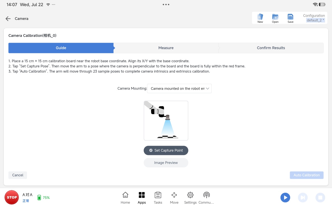
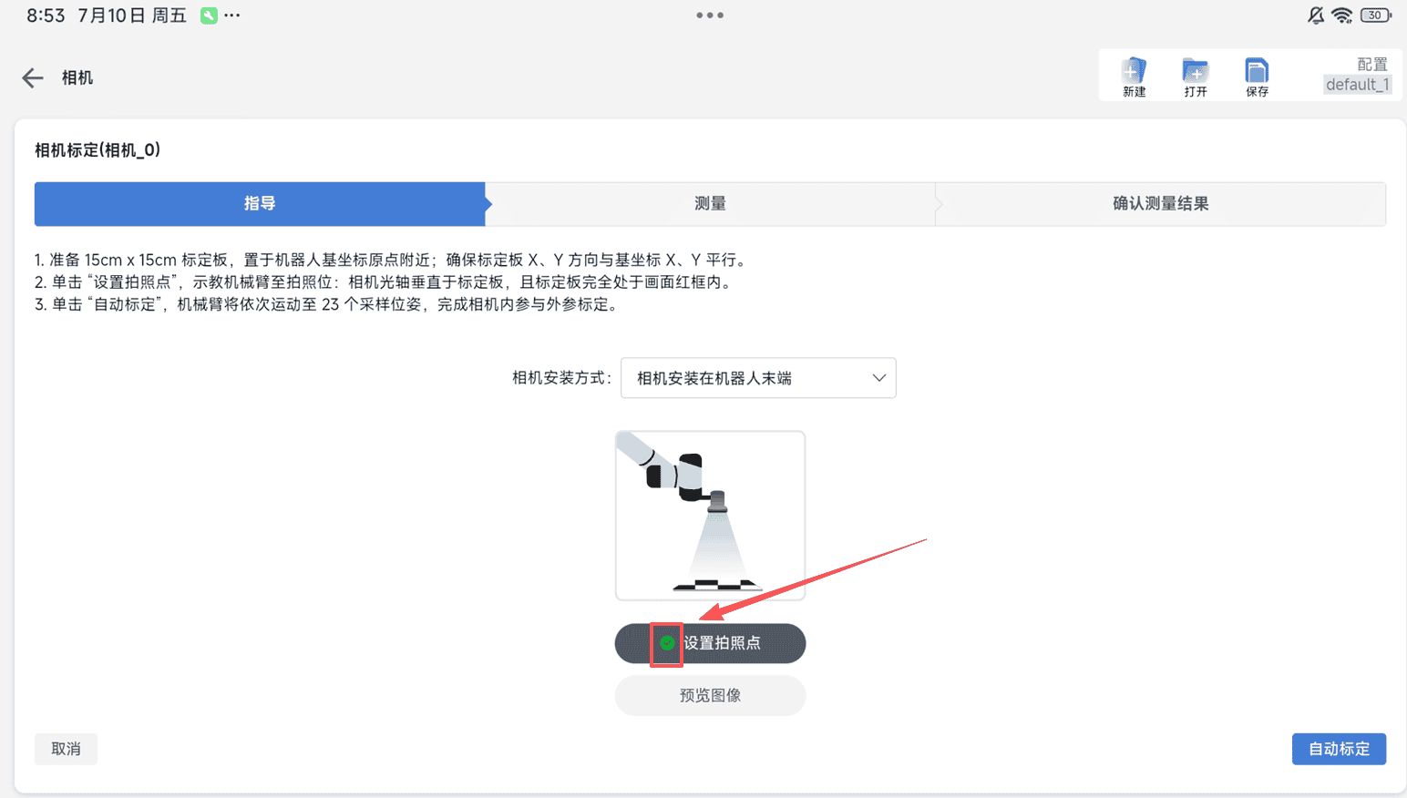
After setting the capture point, check whether a green check mark appears before the [Set Capture Point] item. If it does not appear, check whether any of the preceding steps are incorrect or missing. Then click [Auto Calibration] in the lower-right corner.
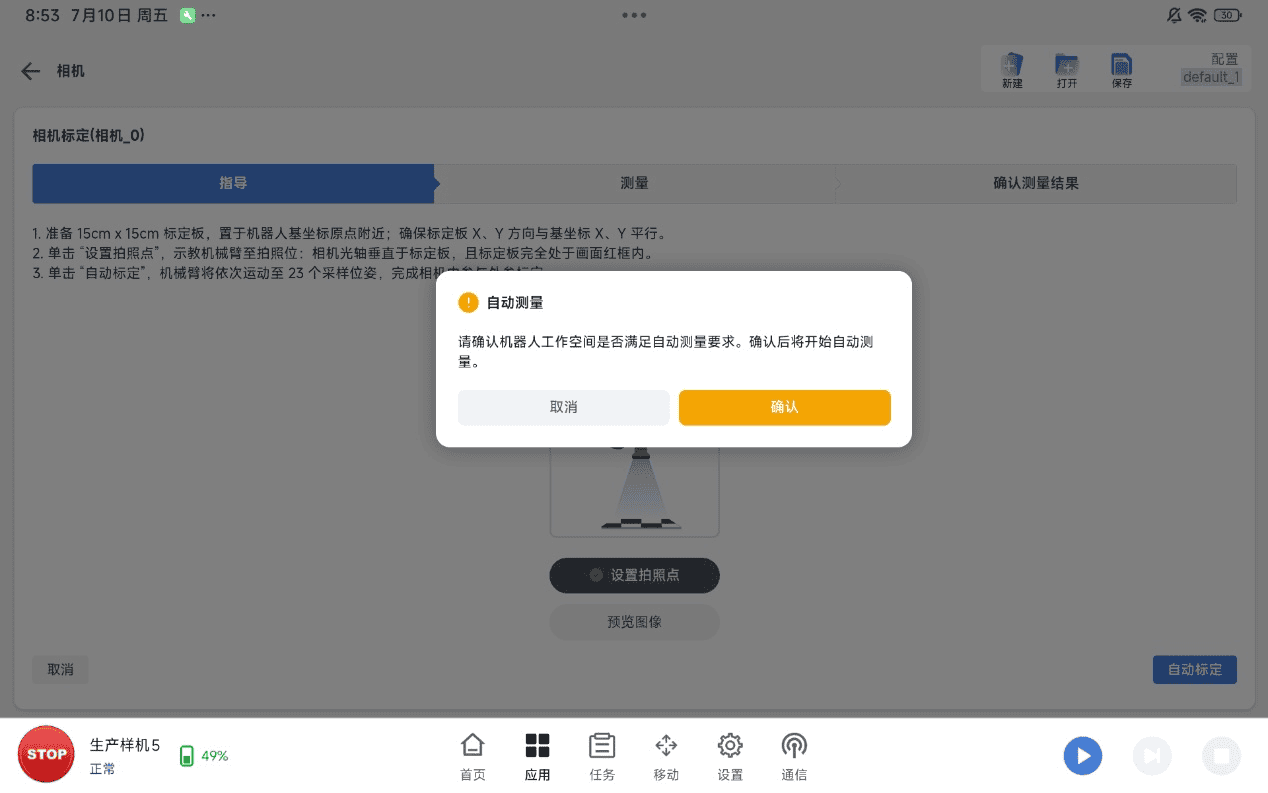
After confirming that everything is correct, click [Confirm] in the pop-up window. The robot then starts automatic calibration.
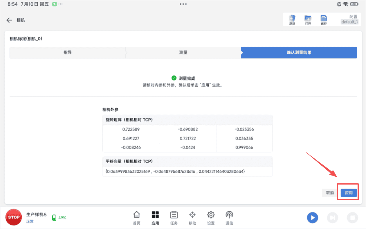
After calibration succeeds, click [Apply].
6. Vision Applications
6.1 Vision Positioning
6.1.1 Vision Positioning Principles and Workflow
The vision positioning function relies on vision nodes and provides a zero-code configuration solution based on Socket communication. Users can complete the entire configuration process through a graphical interface. The system automatically generates the underlying Socket scripts without requiring any manual coding.
- System architecture: Node trigger (camera configuration) > Backend driver > Socket communication > Vision system > Image acquisition and processing > Result output > Program execution.
- Core components:
- Vision node: Selects the camera configuration and triggers the recognition process.
- Camera configuration module: Manages camera communication parameters.
- Communication driver: Controls the task execution logic.
6.1.2 Camera Template Configuration and Parameter Settings
- In the ARCS software, click "Configure > Generally > Camera". The drop-down list displays all supported camera brands.
- Select the driver supported by the selected camera brand. Both 2D and 3D drivers are available.
- Configure the IP address and port number of the camera (server).
6.1.3 Retrieving and Applying Positioning Results
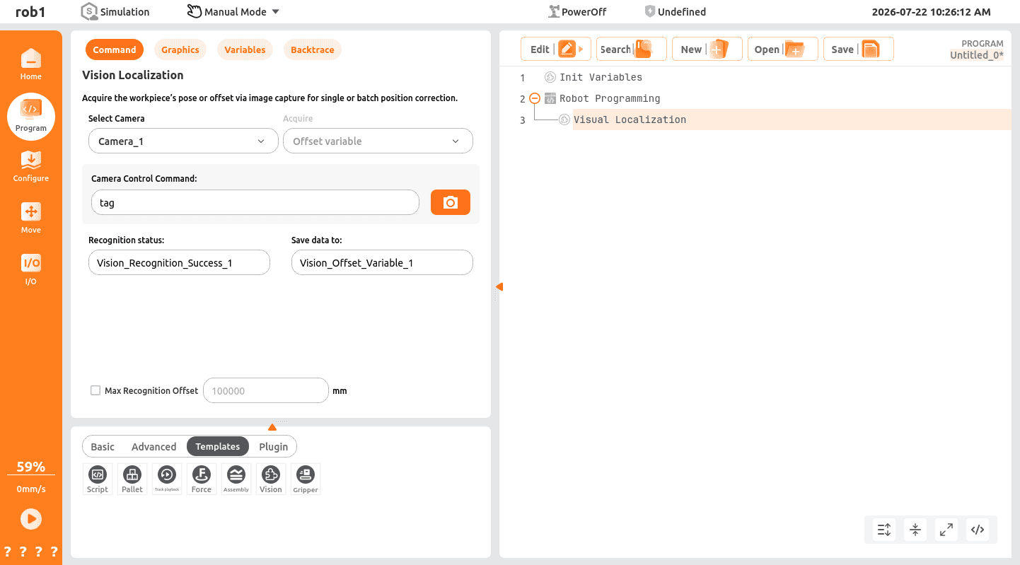
In the ARCS software, click "Program > Templates > Vision". The drop-down list displays all valid camera configurations, including offset-driven cameras and absolute-driven cameras.
Variable types
- Offset-driven cameras support only offset variables.
- Absolute-driven cameras support both offset variables and waypoint variables.
Trigger configuration
Control the camera by sending a specified string to trigger a single image acquisition process.
Variable storage
Stores Socket communication data.
6.2 Vision-Guided Picking
6.2.1 2D Vision-Guided Picking
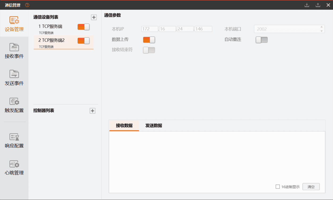
Configure the server network information in Communication Management to establish Socket communication and send/receive strings.
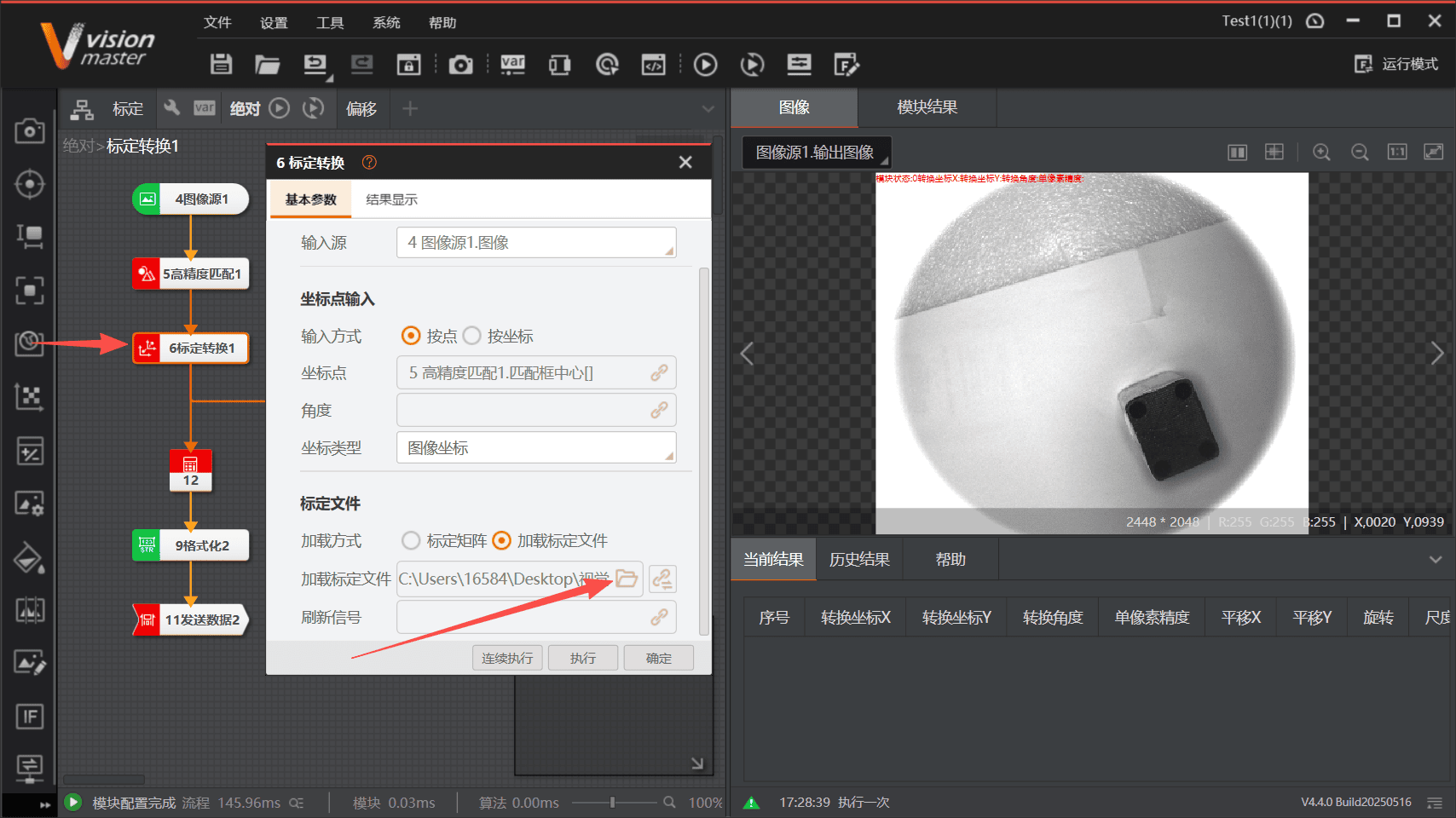
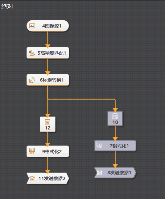
Add a calibration transformation node to the workflow and load the calibration file.
Create the image acquisition and data processing workflow in VisionMaster (VM). Configure different recognition workflows according to the preprocessing method and the returned data type, such as absolute positions or relative offsets.
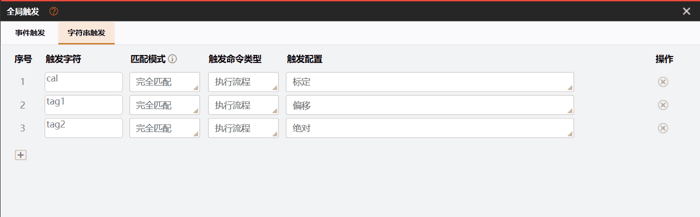
Define the trigger string used to start the VM recognition workflow for image acquisition and data processing.
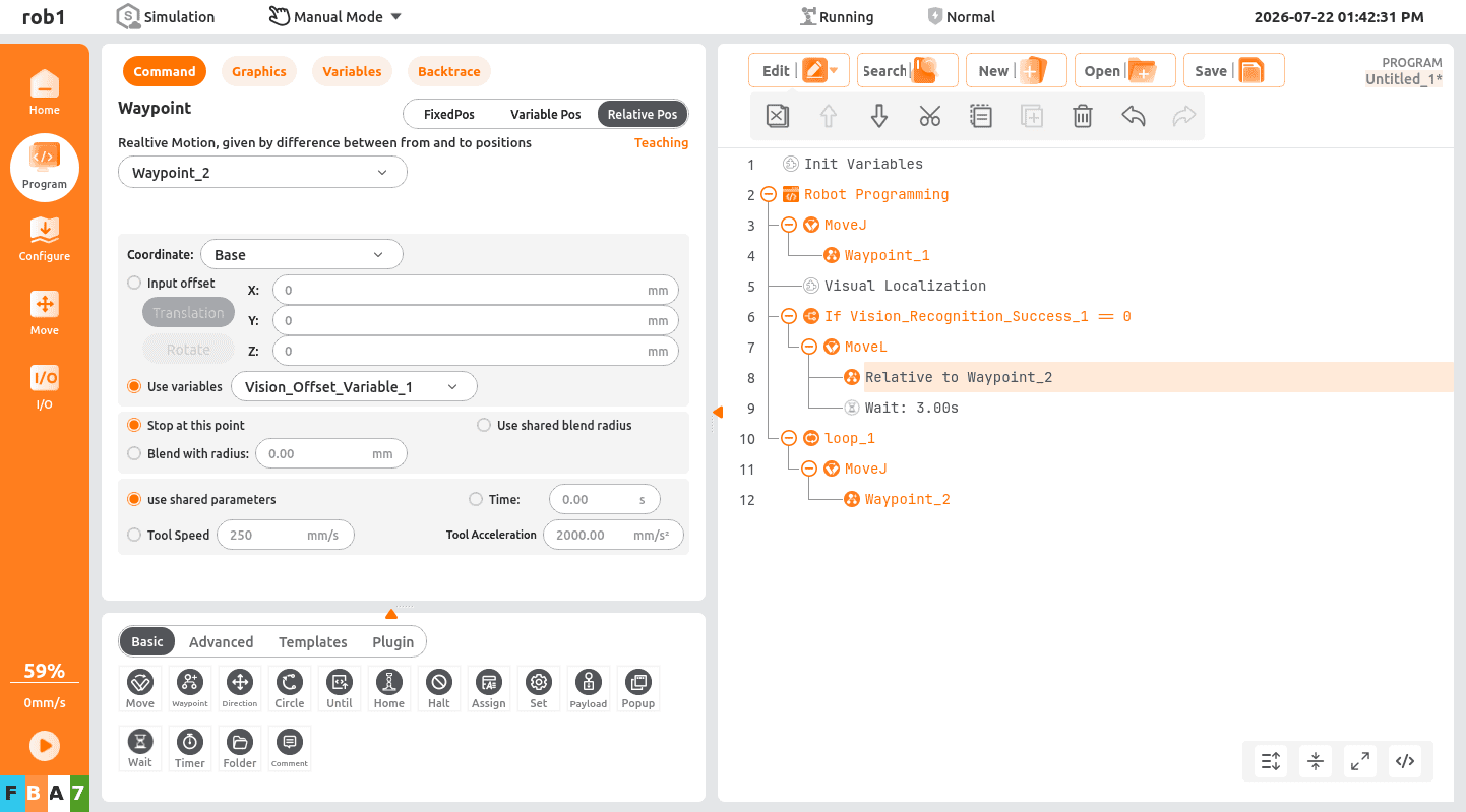
Add a vision node in the ARCS program, configure the camera selection, trigger settings, and result storage variables, then complete the program tree logic for vision-guided picking (or other operations), as shown below.
6.2.2 3D Vision-Guided Picking
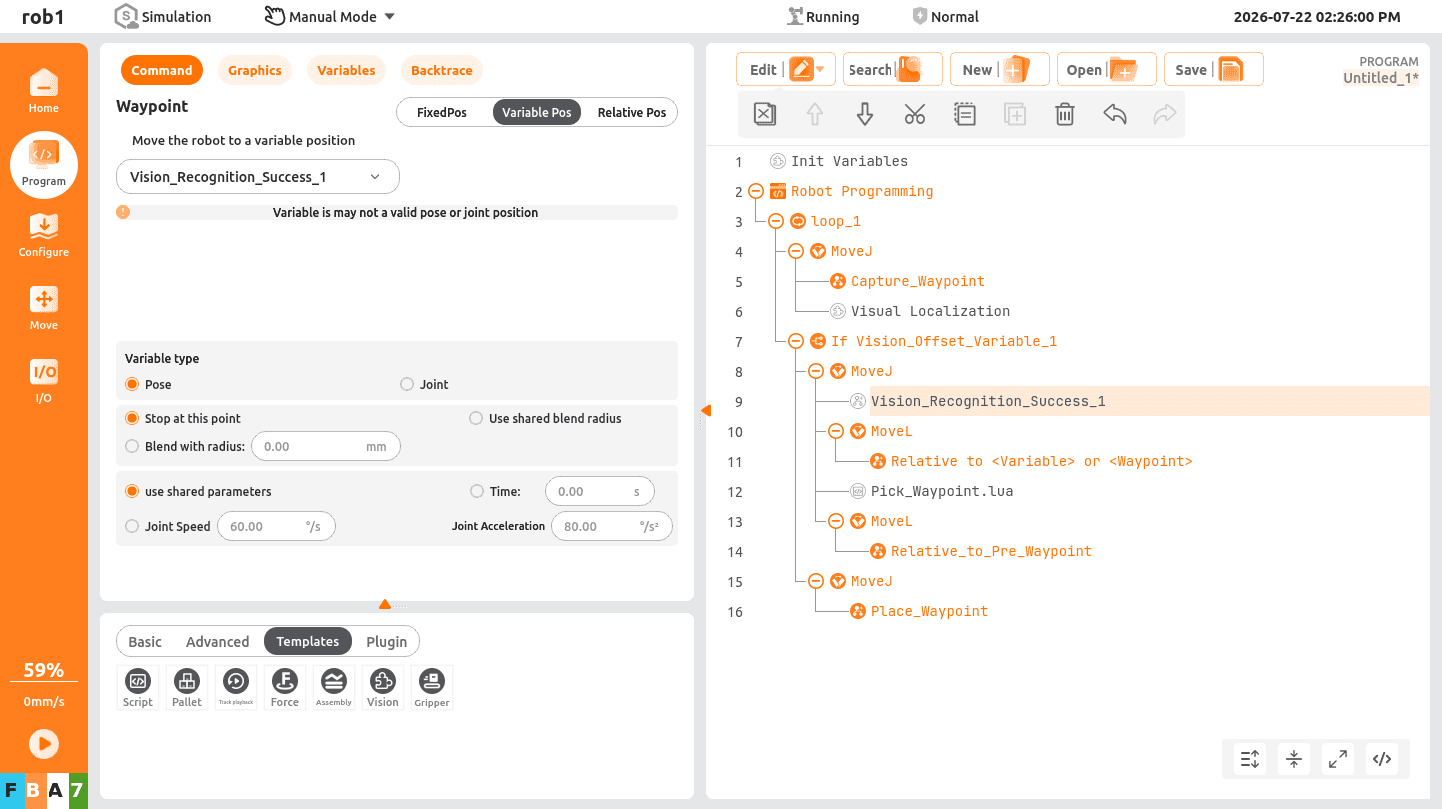
Move the robot so that the camera covers the target picking area, set the current position as the capture point, select the waypoint variable in the vision positioning node, and enter the corresponding object ID.
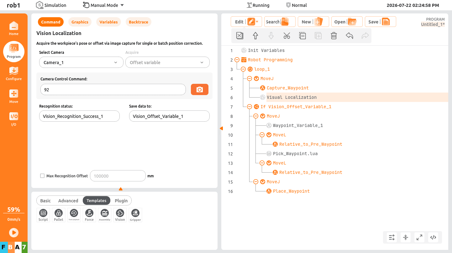
Determine whether the target object has been detected. If detected, move above the object using the stored position variable. Otherwise, exit the loop and continue with the next task.
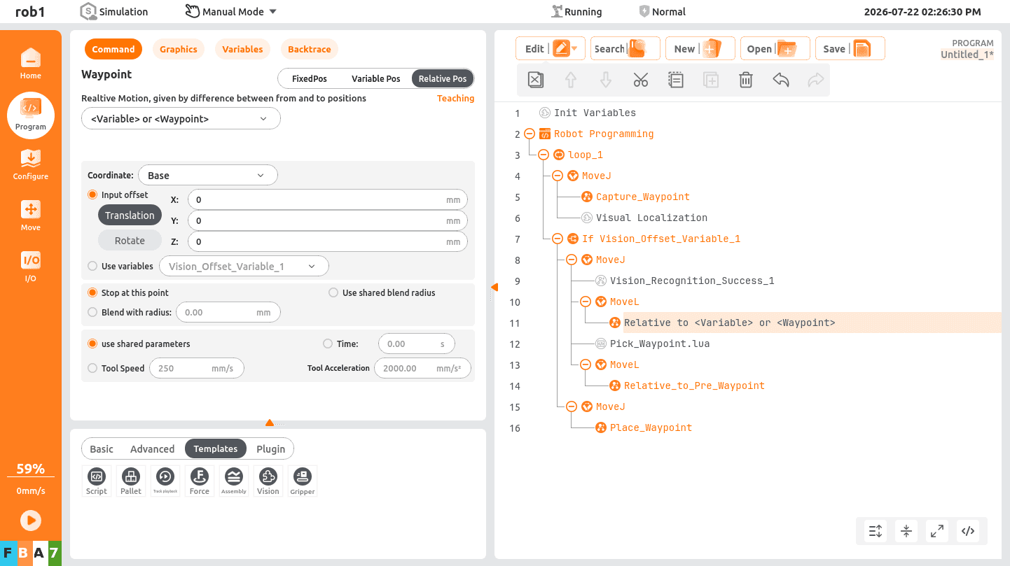
Move linearly to the picking position. Typically, move along the tool coordinate system Z+ direction to position the gripper vertically above the object, then move along the Z- direction to perform the pick before moving to the placement position, preventing collisions caused by unexpected robot motion.
6.2.3 AUBO In-House Camera Vision-Guided Picking
Camera check:
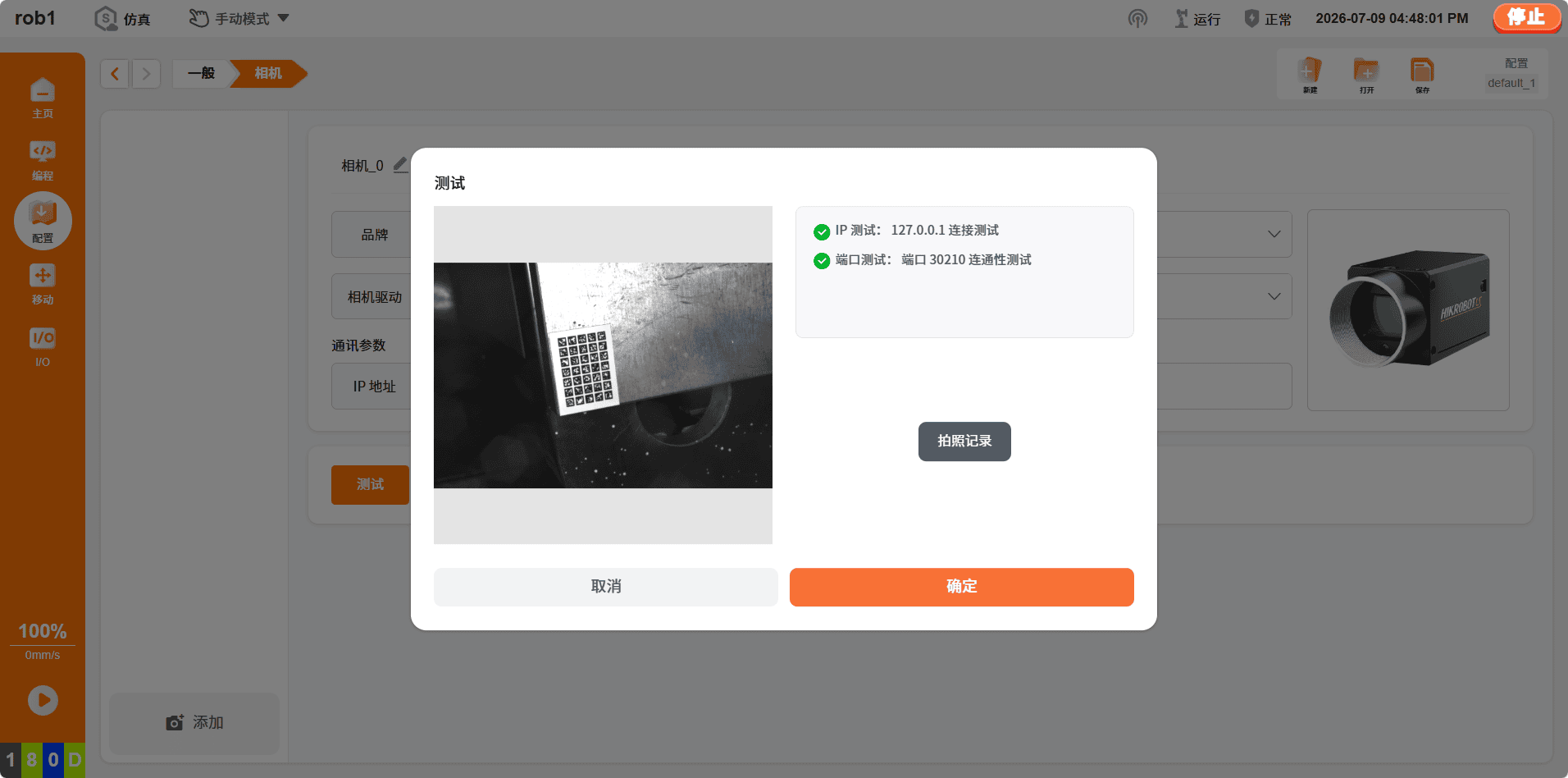
Click "Configure > Generally > Camera" to open the camera page.
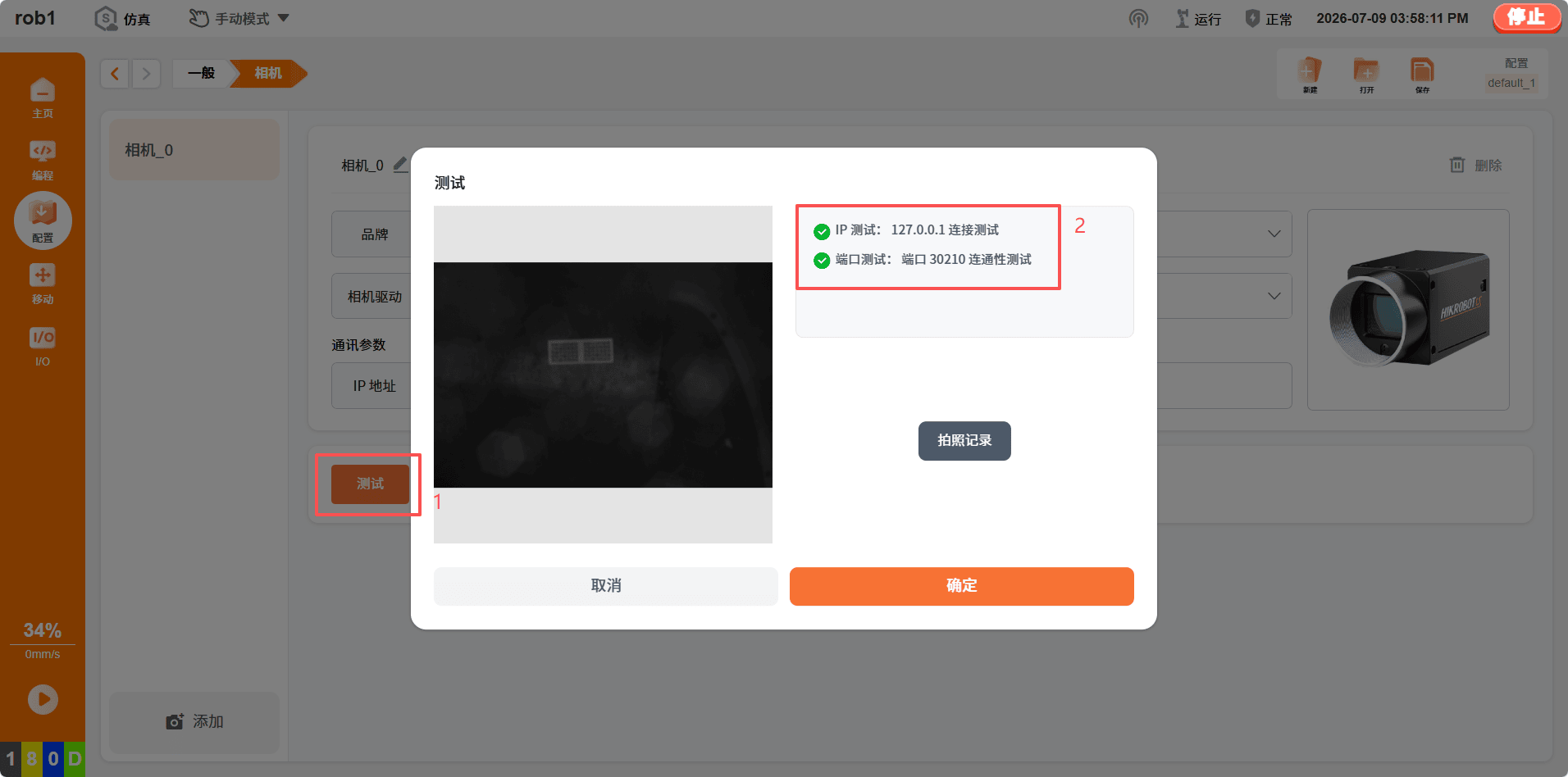
Select the target camera and click [Test]. Confirm that both the IP and port connectivity tests pass. If either test fails, check the camera calibration page for incorrect operations or missed steps.
Gripper check:
This section uses the JunDuo RG75 electric gripper as an example. The gripper is controlled through Modbus RTU.
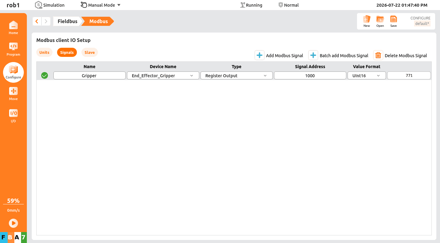
Note:
In the register, enter
1to enable the gripper and0to disable it. Enter779to open the gripper at full speed and full force, and enter1035to close it at full speed and full force.Vision-guided picking scene overview: As shown in the figure,
1indicates the feature code position (capture point),2indicates the picking point, and3indicates the placement point.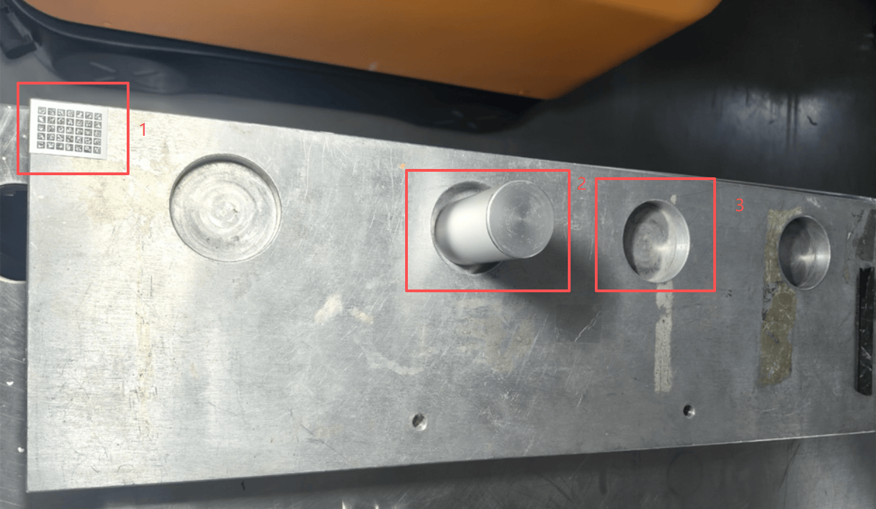
Vision-guided picking programming
Enter the programming interface. The main program consists of three parts: initialization, vision-guided picking, and vision-guided placement.
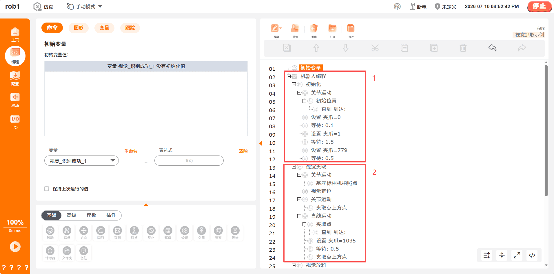
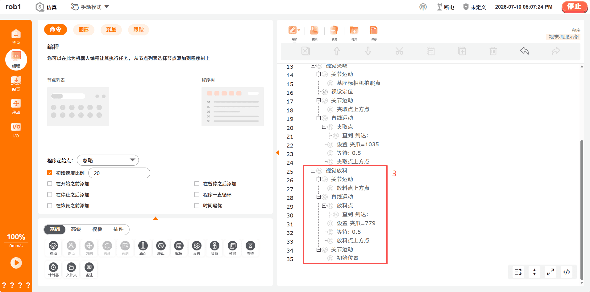
- Initialization: Move the robot arm to the initial position by joint motion and initialize the gripper.
- Vision-guided picking: Move the robot arm to the capture position, capture the feature code, and create the vision coordinate system. During picking, the robot first moves by joint motion to the point above the picking point, then moves linearly to the picking point. After picking the workpiece, it moves linearly back to the point above the picking point.
- Vision-guided placement: During placement, the robot first moves by joint motion to the point above the placement point, then moves linearly to the placement point. After releasing the workpiece, it moves linearly back to the point above the placement point, and finally moves by joint motion to the initial position.
Note:
If the nodes in the program are not consecutive Waypoint nodes, add an Until node at the end of the node to prevent subsequent actions from starting before the robot motion is complete.
Pose requirements: The camera and feature code must form an angle of 10°–40°. The feature code in the field of view must be clear with distinct black-and-white contrast. You can click [Test] on the "Configure > Generally > Camera" page to check whether the feature code is clear and centered in the camera field of view.
Note:
When saving the capture point, set the coordinate system to Base.
Using vision positioning
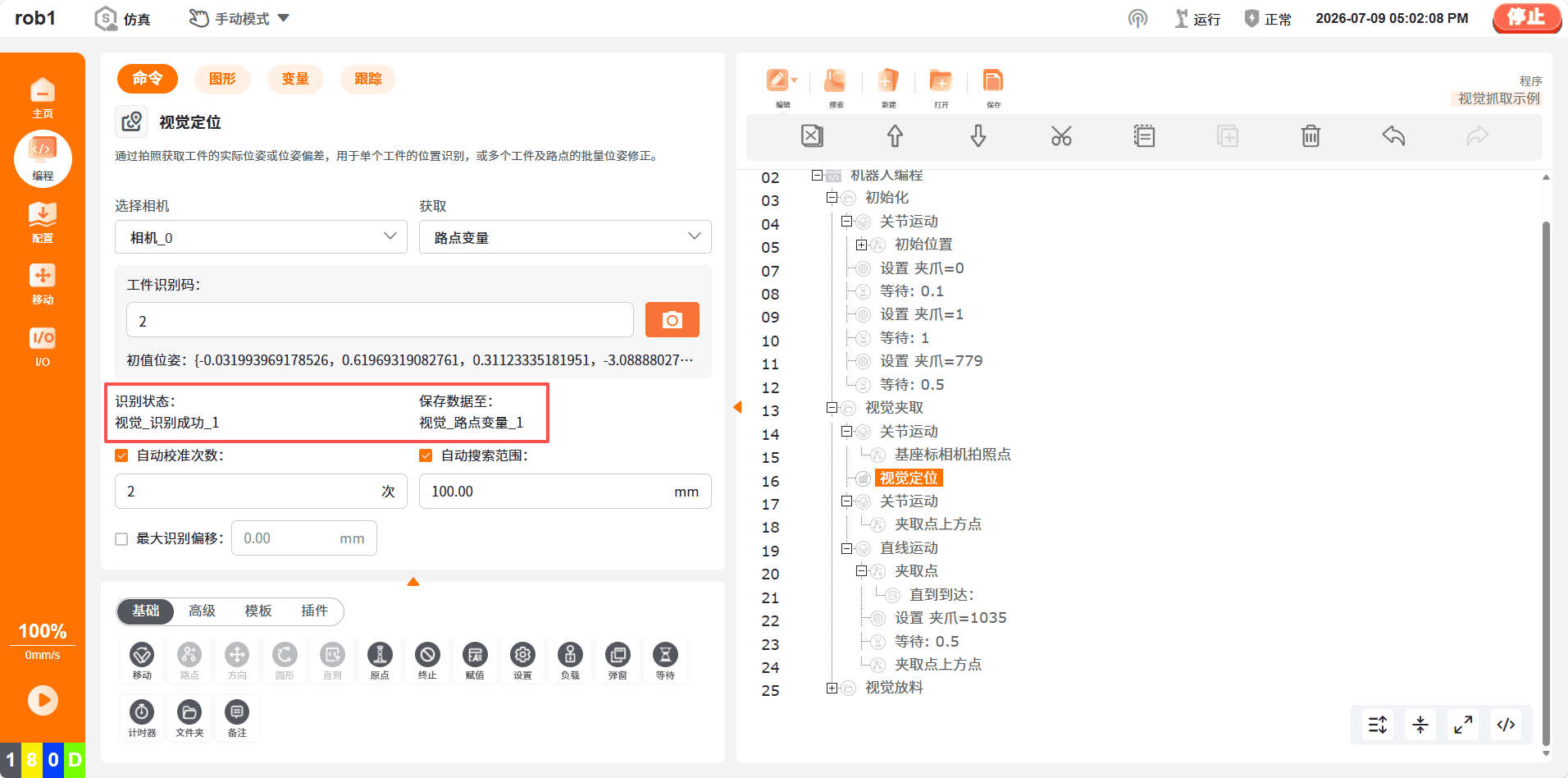
On the programming page, click "Program > Templates > Vision".
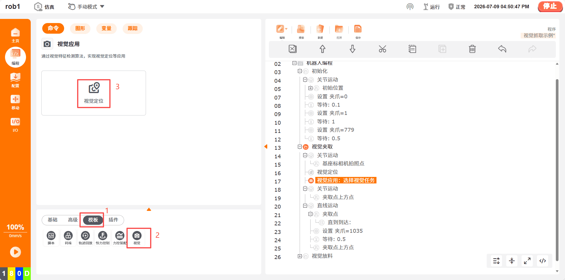
Select the target camera.
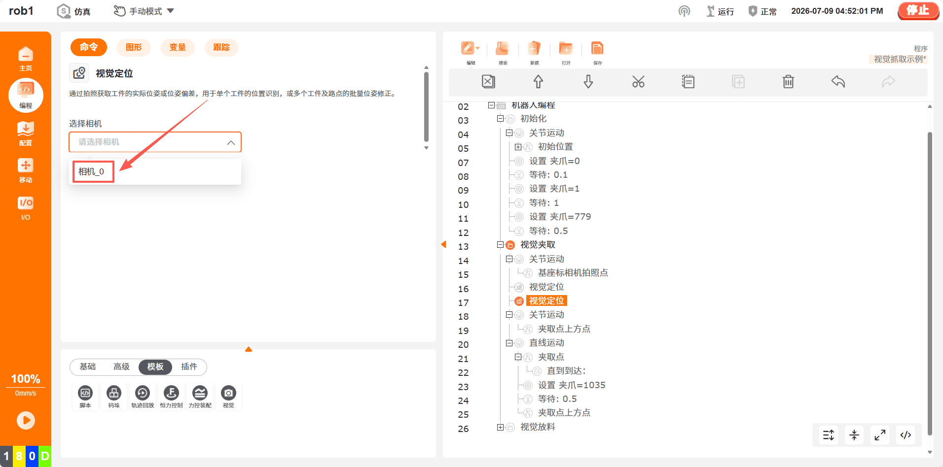
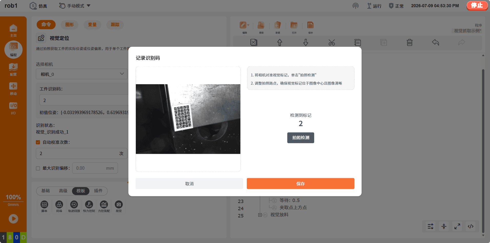
Enter
2as the workpiece recognition code (2indicates that the feature code type is 2), and click the camera icon on the right to take a picture.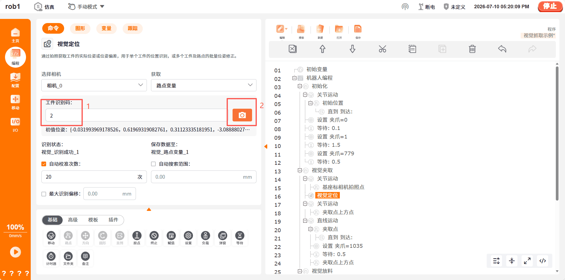
Vision positioning node function description:
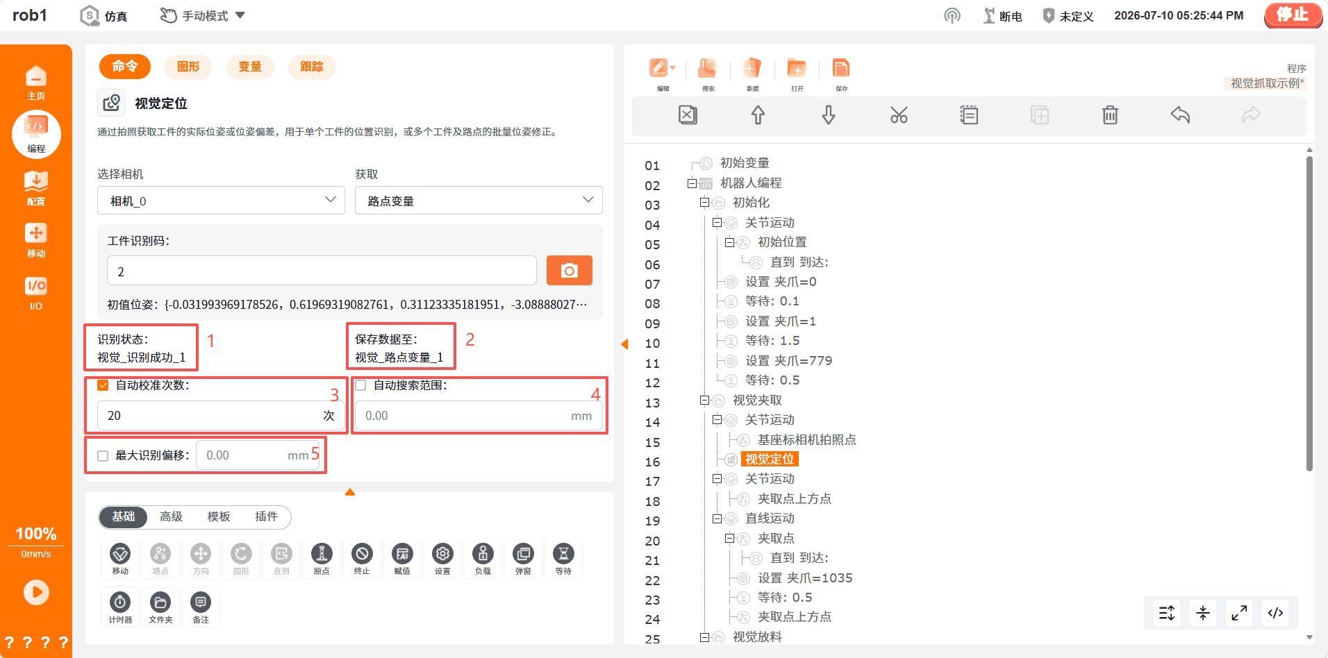
Status variable indicating whether the vision node recognition is successful.
Vision coordinate system saved after capturing the feature code.
Automatic calibration count: the maximum number of captures if the capture result does not meet expectations after vision positioning.
Automatic search range: the maximum distance that the robot arm searches in each direction if the feature code is outside the field of view.
Warning:
The Automatic Search Range function is currently in beta and may cause robot collisions. Use it with caution.
Maximum recognition offset: If the distance between the feature code and the recognized position exceeds this value, recognition is determined to have failed.
Confirm again that the feature code is clear and centered. After confirming that it is correct, click [Save]. If the robot arm pose needs to be modified, make sure to update the camera capture point in the base coordinate system accordingly.
After confirmation, the vision system generates the corresponding coordinate system based on the feature code. Subsequent picking points and placement points must be taught in this vision coordinate system.
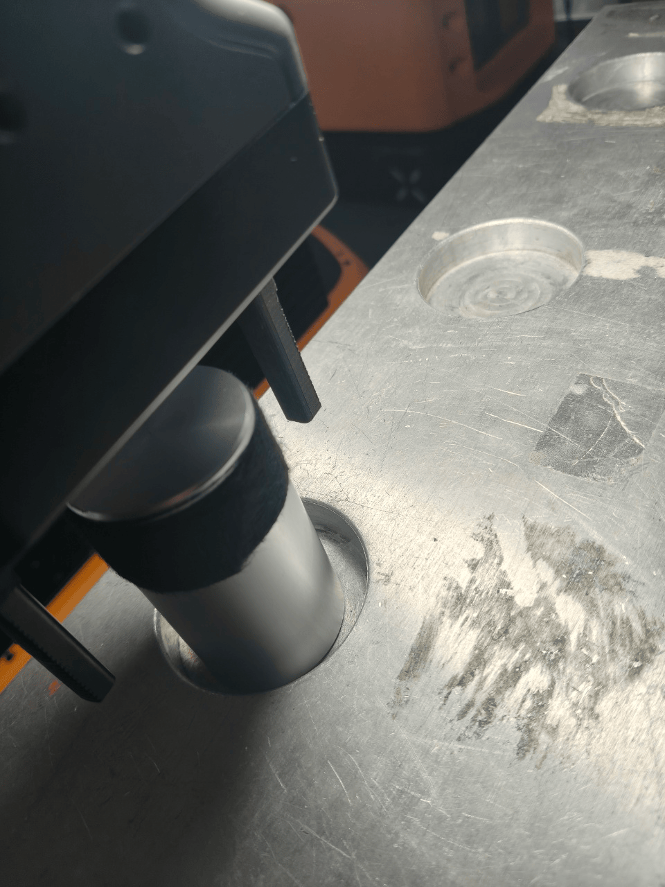
Teach the picking point and the point above the picking point, as shown below:
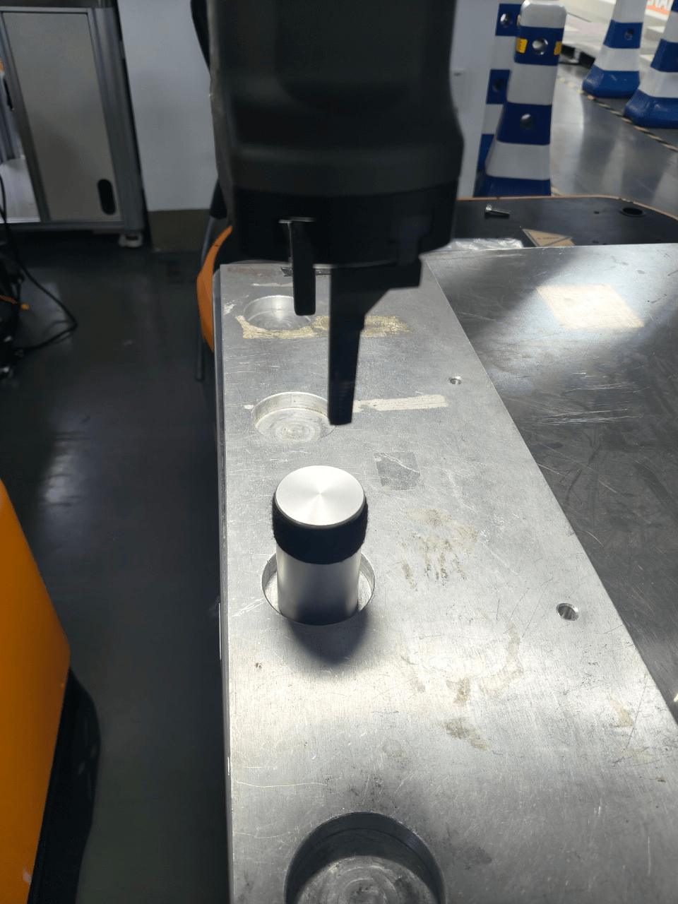
Vision-guided placement.
Teach the placement point and the point above the placement point, as shown below:
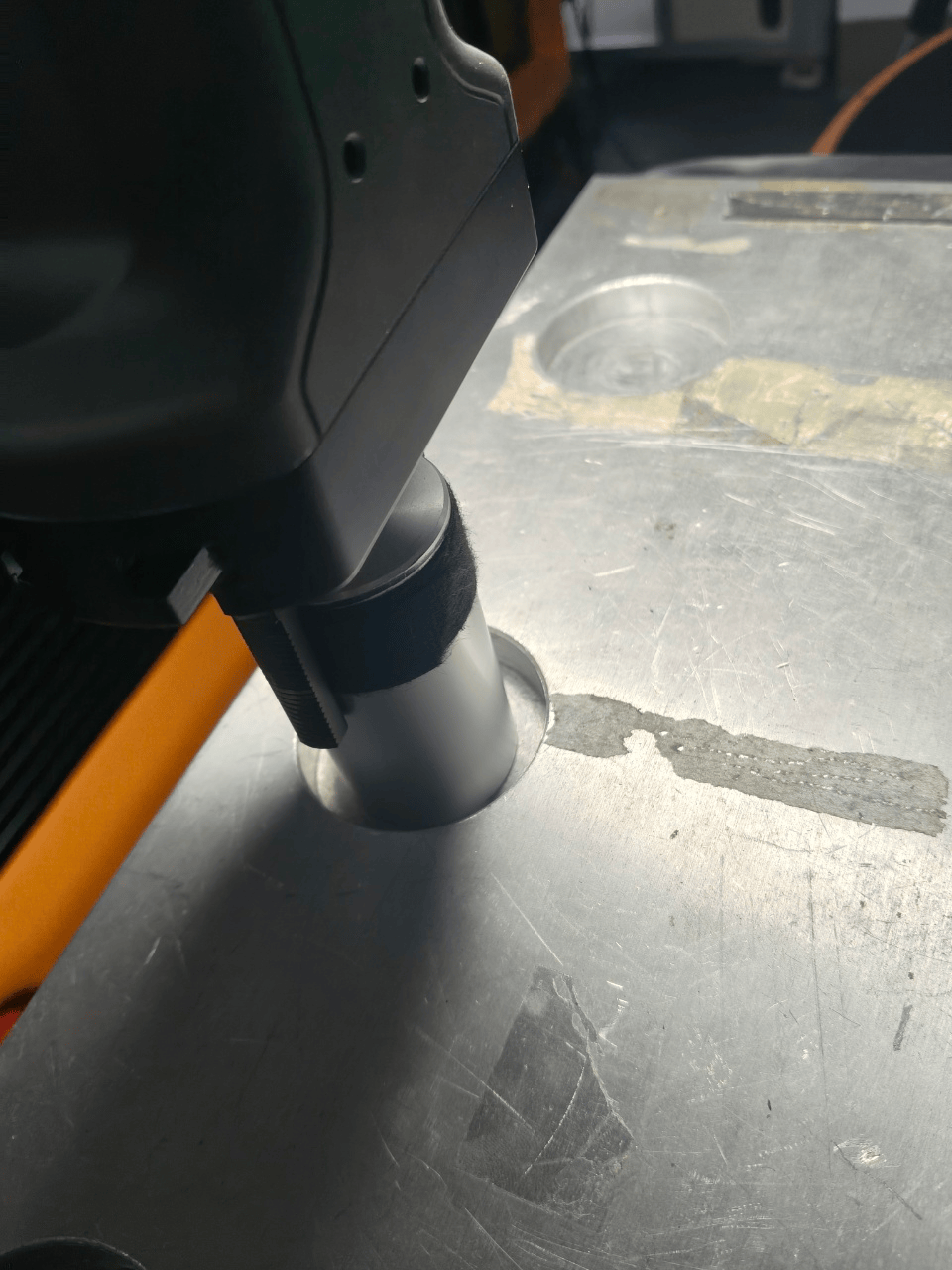
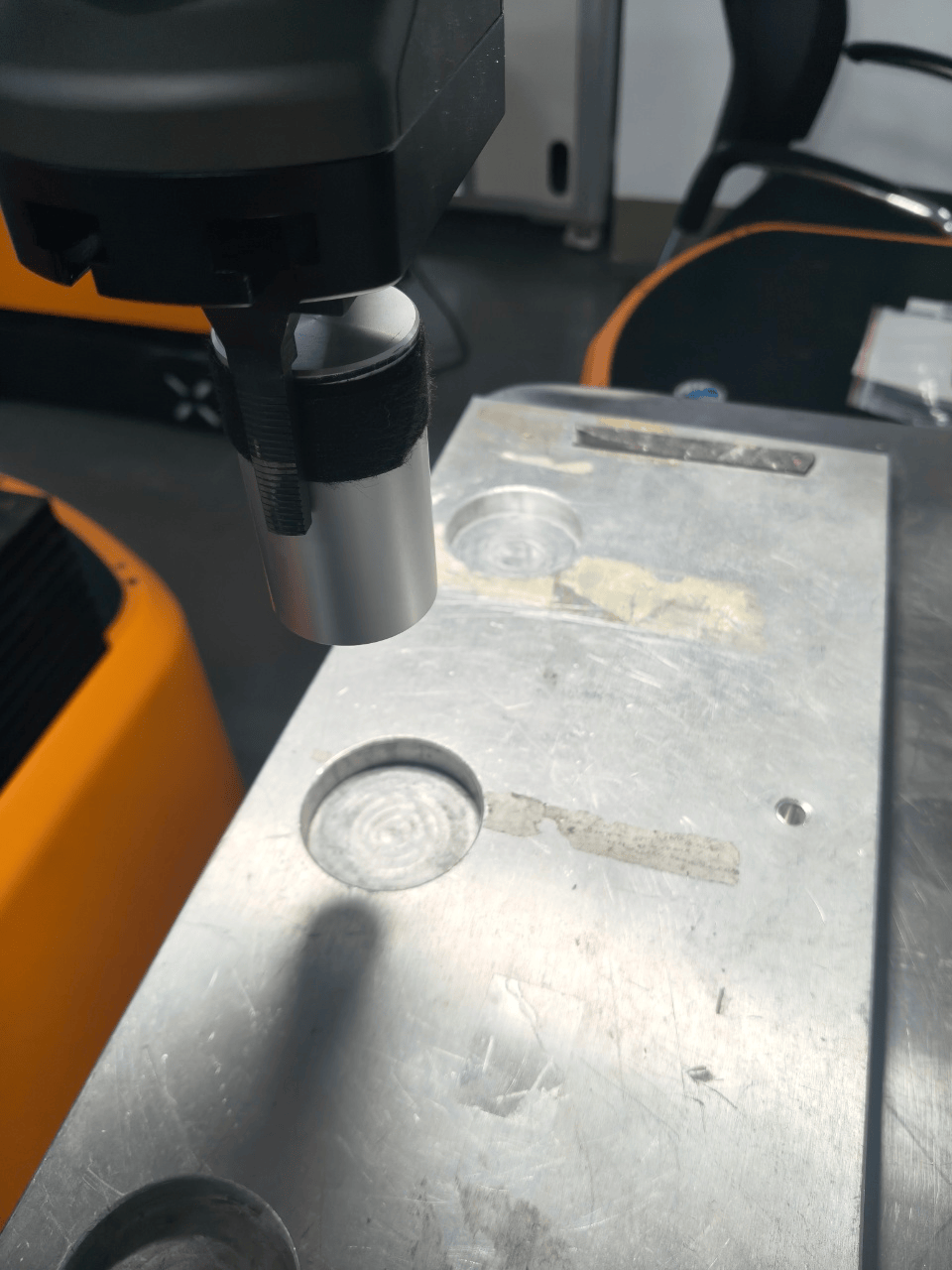
Complete vision-guided picking process demonstration:
6.3 Script Programming
Script programming provides the core capability for customized vision application development. In addition to basic communication functions, it supports advanced features such as vision result processing, motion control, and logical decision-making.
Zero-Code Vision Positioning Configuration
The ARCS system provides a visual configuration interface for vision positioning, allowing users to complete basic vision communication without writing any code:
System architecture: Node trigger (camera configuration) > Backend driver > Socket communication > Vision system > Image acquisition and processing > Result output > Program execution.
Core components:
Vision node: Triggers the camera recognition workflow.
Camera configuration module: Manages camera communication parameters.
Communication driver: Controls the task execution logic.
Configuration procedure:
- In the ARCS software, click "Configure > Generally > Camera", then select the corresponding camera driver (2D or 3D).
- Configure the IP address and port number of the camera server.
- In the programming interface, click "Program > Templates > Vision" and add the corresponding vision node.
- Configure the trigger string and result storage variables. The system automatically generates the underlying communication scripts.
Vision Offset Control Script
Fixed waypoint offset: Suitable for vision compensation based on a single waypoint. The offset is applied relative to the capture waypoint.
Fixed Waypoint Offset
lua-- Get the reference capture waypoint. local take_photo_pose = get_waypoint_pose("take_photo") -- Vision recognition result (unit: meters). local offset_x = 0.02 local offset_y = -0.01 local offset_z = 0 -- Calculate the target waypoint. local target_pose = { take_photo_pose[1] + offset_x, take_photo_pose[2] + offset_y, take_photo_pose[3] + offset_z, take_photo_pose[4], take_photo_pose[5], take_photo_pose[6] } -- Move the robot to the target waypoint. movej(target_pose, 100, 50)Coordinate System Offset: Suitable for scenarios where multiple associated waypoints need to be offset simultaneously. After the coordinate system is offset, all associated waypoints are updated automatically.
Coordinate System Offset
lua-- Get the reference user frame. local ref_coord = get_user_frame("ref_coord") -- Apply an offset to the user frame (X +200 mm, Z -200 mm). ref_coord[1] = ref_coord[1] + 0.2 ref_coord[3] = ref_coord[3] - 0.2 -- Update the user frame. set_user_frame("ref_coord", ref_coord) -- All waypoints that use this user frame will automatically apply the offset. movej("work_point_1", 100, 50) movej("work_point_2", 100, 50)
7. Frequently Asked Questions
Issue: What should I do if VM cannot connect to the camera?
Solution: VM may fail to connect to the camera because the connection cable is loose or the camera IP address is not on the same subnet as the computer. Check and reconnect the cable, and ensure that the camera IP address and the computer IP address are on the same subnet. After changing the IP address, restart both the camera and the computer before reconnecting.
Issue: What should I do if the IPC and the camera cannot communicate?
Solution: Ensure that the IPC and camera can communicate over the network. Use the
pingcommand to verify connectivity. For example,172.17.1.4and172.17.1.2should be able to communicate successfully. If the camera IP address is not configured within the reachable network, communication cannot be established.Issue: Why is the recognition rate low when picking objects from deep bins or containers, and why are only the top-layer objects detected?
Solution: The depth capture range of the Mech-Eye camera does not fully cover the container depth. Increase the depth range so that it completely covers the container.
Issue: Why does ARCS report a recognition timeout even though the IPC detects the object successfully, or why does the program node time out after successful recognition?
Solution: Check the network connections between the IPC, switch, camera, and ARCS controller. Ensure that all network links operate at 1 Gbps (1000 Mbps) or higher and that all cables are securely connected.
Issue: How can I reduce recognition errors for irregularly arranged objects?
Solution: Increase the confidence threshold in Mech-Vision to reduce false detections. After adjustment, verify the recognition results to ensure both high accuracy and a low false recognition rate.
Issue: What should I do if the target waypoint is correct after image capture, but the robot collides with the target object during operation?
Solution: Check the tool configuration in the camera settings and ensure that the selected tool matches the actual end effector. Incorrect tool selection or inaccurate tool parameters may cause a mismatch between the calculated and actual tool positions, resulting in collisions.
Issue: What should I do if the offset waypoint has a large positioning error?
Solution: Check whether the recorded capture pose matches the current image capture pose. If the capture position, camera installation position, or vision node configuration has been changed, record the capture pose again, update the vision node configuration, and verify the offset result.