Fieldbus
Users can configure industrial computer network protocols for real-time distributed control that are acceptable to AuboStudio: EtherNet/IP, Modbus, or PROFINET.
Modbus
Introduction to Modbus
Modbus is an important communication protocol in industrial automation control systems. It has the characteristics of strong debugging ability, large data transmission volume, good real-time performance, etc. External devices (such as PLC) can establish connections with the robot via the Modbus protocol, and the robot can also communicate with the external devices as a Modbus slave.
The Modbus protocol includes Modbus RTU and Modbus TCP versions.
- Modbus RTU: It uses serial communication, represents data in a binary and compact way, and requires a checksum with cyclic redundancy check. Modbus RTU is mainly used in industrial and system automation applications where the communication distance between devices is long.
- Modbus TCP: It uses TCP/IP (such as Ethernet) connections and requires no checksum calculation. Compared with Modbus RTU, Modbus TCP has a faster communication speed and can connect more devices.
You can configure Modbus device information in the system and establish a connection with the Modbus device with a specified IP.

Modbus unit management
- Connect the Modbus device to the controller communication interface.
- Click "Configure > Fieldbus > Modbus > Units." Click [Add Modbus Unit], select the Modbus unit mode, customize the device name and slave number, and set the relevant parameters of the Modbus device.
- Select the device to be deleted and click [Delete Modbus Unit] to delete the device.
Modbus signals management
- After adding a Modbus device, click "Configure > Fieldbus > Modbus > Signals." Click [Add Modbus Signal], customize the signal name, and set the device name, type, and signal address.
- This system provides batch addition of Modbus signals. Click [Batch Add Modbus Signals], customize the signal names, and set the parameters such as device name and type.
- The added Modbus signals can have custom functions. Please refer to "I/O Setup" for details.
- Select the signal to be deleted and click [Delete Modbus Signal] to delete the signal.
Modbus slave management
The robot can also be used as a Modbus slave. Please refer to the ARCS Modbus User Guide for more details.
PROFINET
PROFINET is a network protocol that allows you to enable or disable the robot's link to the PROFINET controller.
EtherNet/IP
EtherNet/IP Introduction
EtherNet/IP is an industrial Ethernet protocol based on the TCP/IP protocol stack, established by ODVA (Open DeviceNet Vendor Association) and widely used for real-time data exchange between industrial automation devices. Its core advantages include:
- Strong Compatibility: Supports interconnection with various industrial devices such as PLCs, robot arms, and sensors, and is compatible with devices from mainstream manufacturers (Inovance, Omron, Siemens, etc.);
- High Real-time Performance: Adopts a "producer-consumer" communication model, enabling millisecond-level data transmission to meet real-time control requirements in industrial scenarios;
- Flexible Configuration: Standardizes device descriptions through EDS (Electronic Data Sheet) files, simplifying the adaptation process between different devices.
Usage
1. Hardware Connection
- Connect the ARCS controller to the industrial network via an Ethernet cable.
- Ensure network parameters are configured correctly.
- Verify that the physical connection status is correct.
2. EIP Service Configuration
On the teach pendant home page, navigate to "Configure > Fieldbus > EtherNet/IP" to configure the EIP service.
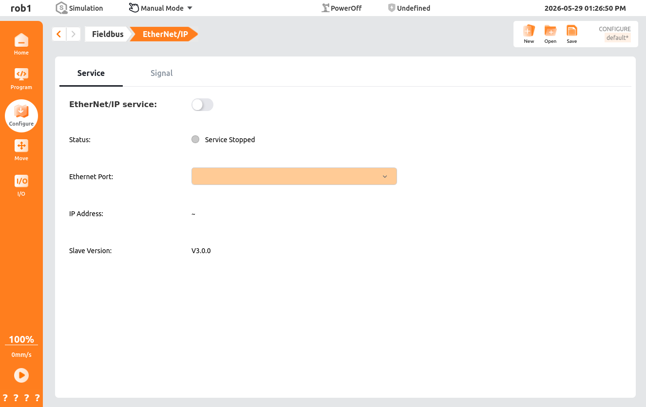
EIP Service Page Functions:
- EtherNet/IP Service: Turn the EIP service on/off.
- Status: Displays service closed / master disconnected / master connected.
- Network Port: Defaults to the currently active network port; can be manually selected when the service is closed.
- IP Address: Displays the IP address of the currently active network port.
- Slave Version: Displays the EIP software version number (displayed after the master connects).
EIP Signal Page Functions:
- Signal List: EIP signal list.
- Add: Add an EIP signal.
- Delete: Delete an EIP signal.
- Name: Supports Chinese/English names.
- Signal Type:
- Input: Input signals used to receive control commands or status feedback signals sent by external devices (such as PLCs and sensors).
- Output: Output signals used to send robot status, execution results, or control command signals to external devices.
- Address Offset.Bit Offset:
- Offset Address:
- Input: 88-150 (even numbers only).
- Output: 182-244 (even numbers only).
- Bit Offset: Binary Boolean type bit offset (0~15).
- Offset Address:
- Type: Boolean, signed integer, unsigned integer, float, swapped float, binary, hexadecimal.
3. Programming Usage
Use EIP signals directly in programs without the need for indirect read/write through server registers or Modbus:
| Program Node | EIP Usage |
|---|---|
| Assignment | EIP input/output signals can be used as variables |
| Set | EIP output signal values can be set (register and Boolean types) |
| Wait | Wait for EIP signal conditions to be met (e.g., EIP_1=88, EIP_2=true) |
| Until | EIP condition judgment; if met, skip the direction node |
| Loop | EIP conditions as loop conditions |
| If/Else If | EIP conditions as branch judgments |
| Switch | EIP conditions as branch expressions |
| Subprogram | Call EIP subprogram signals |
4. IO Monitoring
Monitor EIP signal values directly on the IO interface, in the same format as the data types configured for the signals.